
SLIDE 1
1
- Prof. S. Ben-Yaakov , DC-DC Converters
[1-1]
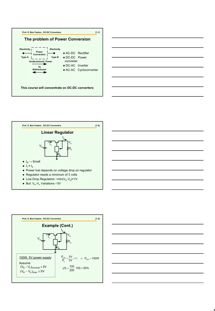
The problem of Power Conversion
Power Conversion Electricity Type A Electricity Type B Uniderectional Power Or Bidirectional
This course will concentrate on DC-DC converters
AC-DC Rectifier DC-DC Power
converter
DC-AC Inverter AC-AC Cycloconverter
- Prof. S. Ben-Yaakov , DC-DC Converters
[1-2]
Linear Regulator
Vin Ro IB Vo I1 I2
IB → Small I1 ≈ I2 Power lost depends on voltage drop on regulator Regulator needs a minimum of 3 volts Low Drop Regulators ~min(Vin-Vo)=1V But: Vin-Vo Variations ~3V
- Prof. S. Ben-Yaakov , DC-DC Converters
[1-3]
Example (Cont.)
W 100 P ; 1 V 5 V 5 P P
loss
- loss
= → = =
100W, 5V power supply Assume: V 3 ) V V (
al min no
- in
≈ − V 5 ) V V (
max
- in