
SLIDE 1
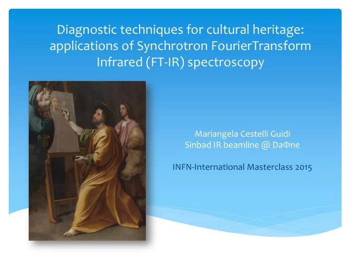
Diagnostic techniques for cultural heritage: applications of Synchrotron FourierTransform Infrared (FT-IR) spectroscopy
Mariangela Cestelli Guidi Sinbad IR beamline @ DaFne INFN-International Masterclass 2015
applications of Synchrotron FourierTransform Infrared (FT-IR) - - PowerPoint PPT Presentation
Diagnostic techniques for cultural heritage: applications of Synchrotron FourierTransform Infrared (FT-IR) spectroscopy Mariangela Cestelli Guidi Sinbad IR beamline @ Da F ne INFN-International Masterclass 2015 Layout The scientific
Mariangela Cestelli Guidi Sinbad IR beamline @ DaFne INFN-International Masterclass 2015
Visible and IR light are both EM radiation, differing only for the
Wavelength l (mm) Frequency n (Hz: n=c/l) Energy E (eV: E=hn) Wavenumber 𝜉 (cm-1)
𝝃 (cm-1)= 1/l (cm)
E total = E translational + E rotational + E vibrational
In the simple case of two point charges, one with charge +q and the other one with charge −q, the electric dipole moment p is: d is the displacement vector pointing from the negative charge to the positive
charge to the positive charge.
Electric field of an electric dipole. The dipole consists of two point electric charges of opposite polarity located close together
A molecule of water is polar because of the unequal sharing of its electrons in a "bent"
with negative charge in the middle (red shade), and positive charge at the ends (blue shade). Examples of polar molecules of materials that are gases under standard conditions are: Ammonia (NH3) Sulfur Dioxide (SO2) Hydrogen Sulfide (H2S).
Common examples of non-polar gases are the noble or inert gases, including: Helium (He) Neon (Ne) Krypton (Kr) Xenon (Xe) Other non-polar gases include: Hydrogen (H2) Nitrogen (N2) Oxygen (O2) Carbon Dioxide (CO2) Methane (CH4) Ethylene (C2H4)
M1 M2 𝜉 = 𝑙 𝑛 vibration frequency 𝑛 =
𝑁1∙𝑁2 𝑁1+𝑁2 (reduced mass)
Increasing k (bond strength) the frequency increases Decreasing m, the frequency increases.
Single bonds: C-C, C-O, C-N 800 - 1300 cm-1 Double bonds: C=C, C=O, C=N 1700-1900 cm-1 Triple bonds: C≡C, C ≡O, C ≡N 2000-2300 cm-1 C-H, N-H, O-H 2700-3800 cm-1
𝐹 = (𝑜 + 1
2) hn
(quantized energy levels)
3N-6 (non linear molecule) 3N -5 (linear molecule)
Detector Detector Reflection Transmission IR source Sample
LNF, February 16 2015
Every moving electric charge emits EM radiation. Classic (v<<c) Relativistic (v≈c) 1/𝛿 𝛿 = 1 1 − 𝛾2 𝛾 = 𝑤/𝑑
Per b=0.99 1/g= 10 mrad
Critical energy
Infrared domain from 10 to 103 cm-1 1.24meV to 1.24 eV
DAFNE
Mobile mirror M1 Fixed mirror M1 IR source Detector beamsplitter
The interferogram depends on the optical path difference (OPD) between the two beams The OPD is twice the mirror excursion x. Since the mirror speed v is constant:
OPD= 2n
𝜇 2 (𝑜 = 0, ±1, ±2, … )
OPD= (2n+1) 𝜇
2 (𝑜 = 0, ±1, ±2, … )
Origin of the interferogram: the momocromatic wave
Detector signal OPD
Spectrum Frequency FOURIER TRANSFORM
Origin of the interferogram: the policromatic wave (disccrete frequencies)
Detector signal Spectrum
Origin of the interferogram: the policromatic wave (continuous frequencies)
Detector signal
TRANSMITTANCE
ABSORBANCE
Sample
Preparation of the surface – polishing Thick samples
Crystal n1 Sample n2 Snell’s law: n1 x sini = n2 x sinr Critical angle: r = 90° sinc = n2 / n1 (es. 38° for ZnSe for a sample with n=1.5)
Kazarian et al, Vibrational Spectroscopy 53 (2010) 274–278
CaSO4·2H2O CaSO4.0.5H2O CaSO4
n3 Stretching antisymmetric of SO4 tetrahedra n1 Stretching symmetric of SO4 tetrahedra Water molecule: Stretching symmetric and antisymmetric of H2O
CaSO4·2H2O CaCO3
The microscope is essentially a beam condenser The IR microscope is essentially a beam condenser
Vincent Mazel et al, (2007). Analytical Chemistry. DOI : 10.1021/ac070993k
Figura 1. Sezione stratigrafica di un frammento prelevato dalla veste verde di un dipinto raffigurante la Madonna col Bambino: a) sezione stratigrafia al microscopio ottico in luce visibile; b) immagine ottenuta al microscopio elettronico (SEM); c) mappatura dell’elemento rame (Cu) eseguita mediante spettrometro a raggi X al microscopio elettronico (SEM-EDS); d) distribuzione della resina poliestere ottenuta mediante FTIR FPA-imaging; e) distribuzione del pigmento verde malachite, ottenuta mediante FTIR FPA-imaging; f) distribuzione di legante proteico,
particella verde e del riferimento della malachite; i) spettro della componente proteica e del riferimento del rosso d’uovo; j) spettro ottenuto da una zona contenente olio siccativo e lo spettro di riferimento di una “sapone” formatosi per reazione tra rame e olio siccativo – immagine tratta dal testo citato – nota 3
http://www.vangogh.ua.ac.be/
The darkening of chrome yellow is a phenomenon widely observed on several paintings by Vincent van Gogh such as the famous versions of the Sunflowers. Analysis of artificially aged model samples of lead chromate using the combined use of various synchrotron radiation based analytical techniques (μ-XRD, μ-XANES and µ-FTIR), established that darkening of chrome yellow is caused by reduction of PbCrO4 to Cr2O3.2H2O (viridian green). This is likely accompanied by the presence
(CH3CO2)7Cr3(OH)2 [chromium(III) acetate hydroxide].
Image courtesy of http://www.vangogh.ua.ac.be/
To avoid photo induced darkening of the susceptible variants of the lead chromate-based pigments, it is advisable to minimize their exposure to light with wavelengths shorter than about 525 nm
PbCr1−xSxO4 PbCrO4
What is the alteration mechanism of the chrome yellow pigments?
Micro-X-ray Fluorescence Micro-X-ray Diffraction Micro-Fourier Transform Infrared Spectroscopy Micro-X-ray Absorption Near-Edge
monoclinic
200x600 mm
FPA detector Ossalato 20 mm
Cluster Analysis Principal Component Analysis RGB map of the sample composition
Courtesy of Centro Conservazione e Restauro La Venaria Reale
Solventi Leganti Vernici Fibre Ma anche in alcuni pigmenti inorganici
Olii siccativi Resine naturali Cere Resine sintetiche Additivi Plastiche
Struttura generale di un'ammide. Se R' e R" sono idrogeni l'ammide si dice primaria, se solo uno fra R' ed R" è un H, si dice secondaria, se R' ed R" non sono idrogeni, l'ammide si dice terziaria Tempere all’uovo Tempera grassa Lana e seta Colle animali Cuoio e pelle Caseina Plastica
Carbonati Silicati Solfati Pigmenti organici
Solfati Ossalati Nitrati Saponi
https://web2.infn.it/Dafne_Light/ cestelli@lnf.infn.it