
SLIDE 1
Transactions of the Korean Nuclear Society Virtual Spring Meeting July 9-10, 2020
Design of the Perforated Plate Improving Flow Uniformity in the SFR Steam Generator
V.T. Nguyena, S. Imb*, J. Jungc, S.R. Choic, and B.J. Kima*
aSchool of Mechanical Engineering, Chungnam National University, Daejeon 34134, Korea bDepartment of Mechanical and Control Engineering, Seoul Cyber University, Seoul 01333, Korea cVersatile Reactor Technology Development Division, Korea Atomic Energy Research Institute, Daejeon, Korea *Corresponding author: bjkim@cnu.ac.kr, sunghyuk@iscu.ac.kr
- 1. Introduction
Recently, Korea Atomic Energy Research Institute (KAERI) has proposed the Copper Bonded Steam Generator (CBSG) which consists of heat exchanger modules with cross flow type arrangement: vertical circular tubes for water side and square horizontal channels for sodium side [1]. In this arrangement, uniform sodium flows are required to improve the heat transfer efficiency. The purpose of this study is to
- ptimize a perforated plate leading to uniform sodium
flow by the help of numerical simulations (ANSYS FLUENT) [2]. The flow maldistribution and pressure drop are the main evaluation parameters.
- 2. Numerical methods
Figure 1 shows the heat exchanger for the sodium
- flow. The pipe diameter is 130 mm. The sodium enters
the header and is distributed into 66x33 horizontal
- channels. Therefore, it is important to obtain uniform
sodium flow throughout the 66x33 channels. Each channel is of 4.5 mm x 4.5 mm and the distance between two adjacent channels is 1.2 mm. Based on the Reynolds number similarity, water is used instead of sodium for simulation with following parameters: temperature 25oC at atmospheric pressure 1 bar; inlet velocity is 4.73 m/s.
- Fig. 1. The geometric model for simulation
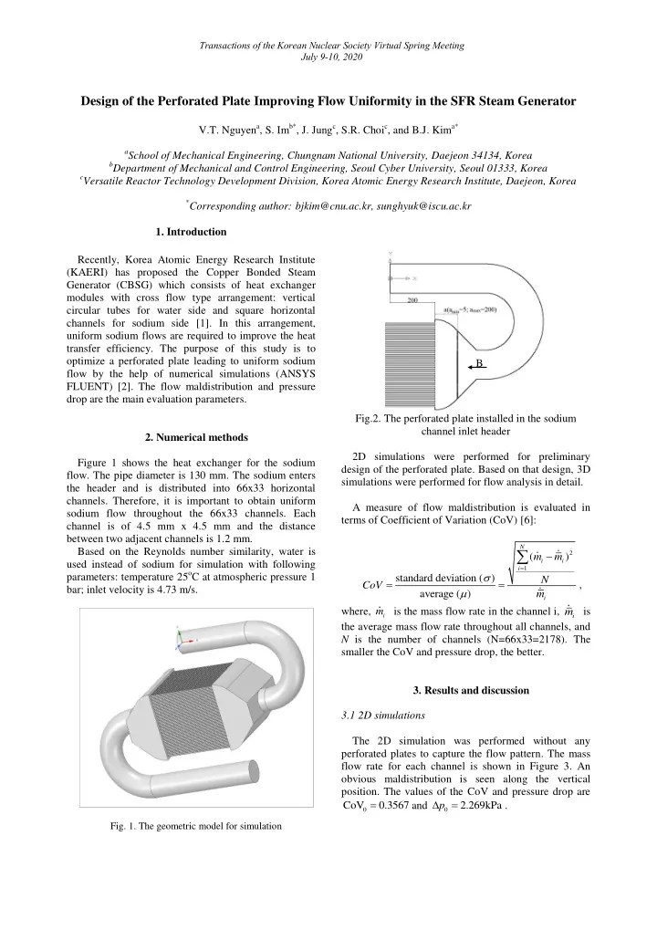
Fig.2. The perforated plate installed in the sodium channel inlet header 2D simulations were performed for preliminary design of the perforated plate. Based on that design, 3D simulations were performed for flow analysis in detail. A measure of flow maldistribution is evaluated in terms of Coefficient of Variation (CoV) [6]:
2 1
( ) standard deviation ( ) average ( )
N i i i i
m m N CoV m
, where,
i
m is the mass flow rate in the channel i,
i
m is the average mass flow rate throughout all channels, and N is the number of channels (N=66x33=2178). The smaller the CoV and pressure drop, the better.
- 3. Results and discussion
3.1 2D simulations The 2D simulation was performed without any perforated plates to capture the flow pattern. The mass flow rate for each channel is shown in Figure 3. An
- bvious maldistribution is seen along the vertical
- position. The values of the CoV and pressure drop are
0.
- 7