Beyond TCAMs: An SRAM-based Parallel Multi-Pipeline Architecture for - - PDF document

beyond tcams an sram based parallel multi pipeline
SMART_READER_LITE
LIVE PREVIEW

Beyond TCAMs: An SRAM-based Parallel Multi-Pipeline Architecture for - - PDF document

Beyond TCAMs: An SRAM-based Parallel Multi-Pipeline Architecture for Terabit IP Lookup Weirong Jiang, Qingbo Wang and Viktor K. Prasanna Ming Hsieh Department of Electrical Engineering University of Southern California Los Angeles, CA 90089,


slide-1
SLIDE 1

Beyond TCAMs: An SRAM-based Parallel Multi-Pipeline Architecture for Terabit IP Lookup

Weirong Jiang, Qingbo Wang and Viktor K. Prasanna

Ming Hsieh Department of Electrical Engineering University of Southern California Los Angeles, CA 90089, USA Email: {weirongj, qingbow, prasanna}@usc.edu

Abstract—Continuous growth in network link rates poses a strong demand on high speed IP lookup engines. While Ternary Content Addressable Memory (TCAM) based solutions serve most of today’s high-end routers, they do not scale well for the next-generation [1]. On the other hand, pipelined SRAM- based algorithmic solutions become attractive. Intuitively multi- ple pipelines can be utilized in parallel to have a multiplicative effect on the throughput. However, several challenges must be addressed for such solutions to realize high throughput. First, the memory distribution across different stages of each pipeline as well as across different pipelines must be balanced. Second, the traffic on various pipelines should be balanced. In this paper, we propose a parallel SRAM-based multi- pipeline architecture for terabit IP lookup. To balance the memory requirement over the stages, a two-level mapping scheme is presented. By trie partitioning and subtrie-to-pipeline mapping, we ensure that each pipeline contains approximately equal number of trie nodes. Then, within each pipeline, a fine-grained node-to-stage mapping is used to achieve evenly distributed memory across the stages. To balance the traffic on different pipelines, both pipelined prefix caching and dynamic subtrie-to- pipeline remapping are employed. Simulation using real-life data shows that the proposed architecture with 8 pipelines can store a core routing table with over 200K unique routing prefixes using 3.5 MB of memory. It achieves a throughput of up to 3.2 billion packets per second, i.e. 1 Tbps for minimum size (40 bytes) packets.

  • I. INTRODUCTION

IP lookup with longest prefix matching is a core function

  • f Internet routers. It has become a major bottleneck for

backbone routers as the Internet continues to grow rapidly [2]. With the advances in optical networking technology, link rates in high speed IP routers are being pushed from OC- 768 (40 Gbps) to even higher rates. Such high rates demand that IP lookup in routers must be performed in hardware. For instance, 40 Gbps links require a throughput of 8 ns per lookup for a minimum size (40 bytes) packet. Such throughput is impossible using existing software-based solutions [3]. Most hardware-based solutions for high speed IP lookup fall into two main categories: TCAM (ternary content ad- dressable memory)-based and DRAM/SRAM (dynamic/static random access memory)-based solutions. Although TCAM- based engines can retrieve IP lookup results in just one clock cycle, their throughput is limited by the relatively low speed

  • f TCAMs. They are expensive and offer little flexibility for

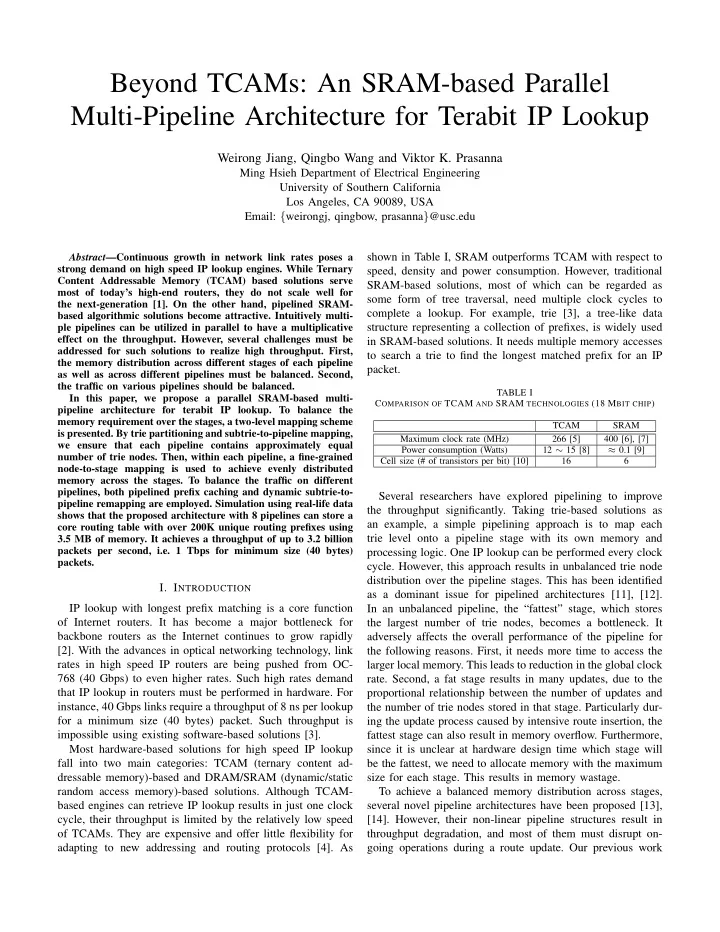
adapting to new addressing and routing protocols [4]. As shown in Table I, SRAM outperforms TCAM with respect to speed, density and power consumption. However, traditional SRAM-based solutions, most of which can be regarded as some form of tree traversal, need multiple clock cycles to complete a lookup. For example, trie [3], a tree-like data structure representing a collection of prefixes, is widely used in SRAM-based solutions. It needs multiple memory accesses to search a trie to find the longest matched prefix for an IP packet.

TABLE I COMPARISON OF TCAM AND SRAM TECHNOLOGIES (18 MBIT CHIP) TCAM SRAM Maximum clock rate (MHz) 266 [5] 400 [6], [7] Power consumption (Watts) 12 ∼ 15 [8] ≈ 0.1 [9] Cell size (# of transistors per bit) [10] 16 6

Several researchers have explored pipelining to improve the throughput significantly. Taking trie-based solutions as an example, a simple pipelining approach is to map each trie level onto a pipeline stage with its own memory and processing logic. One IP lookup can be performed every clock

  • cycle. However, this approach results in unbalanced trie node

distribution over the pipeline stages. This has been identified as a dominant issue for pipelined architectures [11], [12]. In an unbalanced pipeline, the “fattest” stage, which stores the largest number of trie nodes, becomes a bottleneck. It adversely affects the overall performance of the pipeline for the following reasons. First, it needs more time to access the larger local memory. This leads to reduction in the global clock

  • rate. Second, a fat stage results in many updates, due to the

proportional relationship between the number of updates and the number of trie nodes stored in that stage. Particularly dur- ing the update process caused by intensive route insertion, the fattest stage can also result in memory overflow. Furthermore, since it is unclear at hardware design time which stage will be the fattest, we need to allocate memory with the maximum size for each stage. This results in memory wastage. To achieve a balanced memory distribution across stages, several novel pipeline architectures have been proposed [13], [14]. However, their non-linear pipeline structures result in throughput degradation, and most of them must disrupt on- going operations during a route update. Our previous work

slide-2
SLIDE 2

[15] proposed a linear pipeline architecture with a fine-grained node-to-stage mapping scheme to distribute nodes of a leaf- pushed uni-bit trie evenly to different pipeline stages. It can achieve a high throughput of one lookup per clock cycle, as well as support write bubbles [12] for incremental updates without disrupting router operations. However, improvement in memory access speed is rather

  • limited. Thus it becomes necessary to employ multiple

pipelines which can

  • perate

concurrently to speed up IP lookup. Memory and traffic balancing among multiple pipelines become new problems. Similar to the above analysis

  • f how the fattest stage affects the global performance of a

pipeline, the largest pipeline which stores the largest number of trie nodes will become a performance bottleneck of the multi- pipeline architecture. Distinct from TCAM-based solutions, memory balancing is the primary challenge for SRAM-based pipeline solutions. On the other hand, similar to TCAM-based solutions, traffic balancing is needed to achieve multiplicative throughput improvement. Previous works on parallel TCAM- based IP lookup engines use either a learning algorithm to predict the future behavior of incoming traffic based on its current distribution [16], [17], or IP or prefix caching to utilize the locality of Internet traffic [18], [19]. We claim that both schemes can be adapted for SRAM-based solutions. This paper addresses both problems: memory and traffic balancing for an SRAM-based parallel multi-pipeline archi-

  • tecture. This paper makes the following main contributions.
  • To the best of our knowledge, this work is the first

discussion of parallel SRAM-based pipeline solutions for next-generation terabit routers.

  • A novel two-level mapping scheme is proposed to balance

the memory distribution over multiple pipelines and over all pipeline stages.

  • Based on the analysis of current routing tables, a simple

but efficient method is proposed for trie partitioning.

  • Both pipelined prefix caching and dynamic subtrie remap-

ping are incorporated to balance the traffic among multi- ple pipelines.

  • Our results demonstrate that the SRAM-based pipelined

algorithmic solution is a promising alternative to TCAM- based solutions for future high-end routers. The proposed 8-pipeline architecture can store a full core routing table with over 200K unique prefixes using 3.5 MB of memory. It can achieve a high throughput of up to 3.2 billion packets per second, i.e. 1 Tbps for minimum size (40 bytes) packets. The remainder of this paper is organized as follows. Section II reviews the background and related works. Section III pro- poses a parallel architecture with multiple memory-balanced linear pipelines, called the Parallel Optimized Linear Pipeline (POLP) architecture. The two problems of memory and traffic balancing are discussed in Sections IV and V, respectively. Experiments are conducted in Section VI to evaluate the performance of POLP. Section VII concludes the paper.

  • II. BACKGROUND
  • A. Trie-based IP Lookup

01001* P4 010* P3 000* P2 0* P1 111* P8 110* P7 011* P6 01011* P5

1 1 1 1 1 1 1 1

P2 P6 P4 P5 P7 P8 root

(a) (c)

Level 0 Level 1 Level 3 Level 2 Level 4 Level 5 P1

1 1 1 1 1 1 1 1

P2 P3 P6 P4 P5 P7 P8 root

(b)

P1 P3 P3

1

null

  • Fig. 1.

(a) Prefix set; (b) Uni-bit trie; (c) Leaf-pushed uni-bit trie.

The nature of IP lookup is longest prefix matching (LPM). In algorithmic solutions, the most common data structure for LPM is some form of trie [3]. Trie is a binary tree, where a prefix is represented by a node. The value of the prefix corresponds to the path from the root of the tree to the node representing the prefix. The branching decisions are made based on the consecutive bits in the prefix. A trie is called a uni-bit trie if only one bit is used to make branching decision at a time. The prefix set in Figure 1 (a) corresponds to the uni-bit trie in Figure 1 (b). For example, the prefix “010*” corresponds to the path starting at the root and ending in node P3: first a left-turn (0), then a right-turn (1), and finally a turn to the left (0). Each trie node contains two fields: the represented prefix and the pointer to the child nodes. By using the leaf-pushing optimization [20], each node needs only one field: either the pointer to the next-hop address or the pointer to the child nodes. Figure 1 (c) shows the leaf-pushed uni-bit trie derived from Figure 1 (b). Given a leaf-pushed uni-bit trie, IP lookup is performed by traversing the trie according to the bits in the IP address. When a leaf is reached, the prefix associated with the leaf is the longest matched prefix for the IP address. The time to look up a uni-bit trie is equal to the prefix length. The use of multiple bits in one scan can increase the search speed. Such a trie is called a multi-bit trie. The number of bits scanned at a time is called stride. Some optimization schemes [21]–[23] have been proposed to build memory-efficient multi-bit tries.

slide-3
SLIDE 3

For simplicity, we consider only the leaf-pushed uni-bit trie in this paper, though our ideas can be applied to other forms of tries.

  • B. Memory-Balanced Pipelines

A number of researchers have pointed out that using pipelin- ing can dramatically improve the throughput of trie-based

  • solutions. A straightforward way to pipeline a trie is to assign

each trie level to a different stage, so that a lookup request can be issued every clock cycle. However, as discussed earlier, this simple pipeline scheme results in unbalanced memory distribution, leading to low throughput and inefficient memory allocation [13], [24]. Basu et al. [12] and Kim et al. [23] both reduce the memory imbalance by using variable strides to minimize the largest trie level. However, even with their schemes, the size of the memory in different stages can have a large variation. As an improvement upon [23], Lu et al. [25] propose a tree- packing heuristic to balance the memory further, but it does not solve the fundamental problem of how to retrieve one node’s descendents that are not allocated in the following stage. Furthermore, a variable stride multi-bit trie is difficult for hardware implementation especially if incremental updating is needed [12]. Baboescu et al. [13] propose a Ring pipeline architecture for trie-based IP lookup. The memory stages are configured in a circular, multi-point access pipeline so that lookups can be initiated at any stage. The trie is split into many small subtries

  • f equal size. These subtries are then mapped to different

stages to create a balanced pipeline. Some subtries have to wrap around if their roots are mapped to the last several stages. Though all IP packets enter the pipeline from the first stage, their lookup processes may be activated at different stages. Hence all the IP lookup packets must traverse the pipeline twice to complete the trie traversal. The throughput is thus 0.5 lookups per clock cycle. Kumar et al. [14] extend the circular pipeline with a new architecture called the Circular, Adaptive and Monotonic Pipeline (CAMP). It has multiple entrance and exit points so that the throughput can be increased at the cost of output disorder and delay variation. It employs several request queues to manage access conflicts between the new request and the one from the preceding stage. It can achieve a worst-case throughput of 0.8 lookups per clock cycle, while maintaining balanced memory across pipeline stages. Due to the non-linear structure, neither the Ring pipeline nor CAMP under worst cases can maintain a throughput of

  • ne lookup per clock cycle. Also, neither of them supports

well the write bubble proposed in [12] for the incremental route update. Our previous work [15] adopts an optimized linear pipeline architecture, named OLP, to achieve a high throughput of one output per clock cycle. Supporting nops (no-operations) in the pipeline offers more freedom in mapping trie nodes to pipeline stages. After using a fine-grained node- to-stage mapping scheme, trie nodes are evenly distributed across most of the pipeline stages. In addition, OLP supports incremental route updates without disrupting the ongoing IP lookup operations. This paper extends the idea of OLP to map multiple tries to one pipeline, while keeping the memory requirement across stages balanced.

  • C. Parallel IP Lookup Engines

Most published parallel IP lookup engines are TCAM-

  • based. They partition the full routing table into several blocks

and make the search process parallel on different blocks. Power efficiency and througput improvement can be obtained by such parallelism [16]. To partition the routing table, Zane et al. [8] propose two schemes: bit-selection and trie-based architectures. In the former, selected bits are used to index different TCAM blocks

  • directly. However, prefix distribution imbalance among the

TCAM blocks may be quite high, resulting in low worst- case performance. The latter scheme splits the trie by carving subtries out of the full trie. This can have a much better worst- case bound. Subtrie-to-block mapping is implemented using an index logic consisting of a TCAM and an SRAM. Since those subtries may be on different levels of the trie, different numbers of bits are used to index different subtries. Such a scheme is difficult for SRAM-based solutions, where the index tables are addressable memory with a constant number

  • f address bits.

Traffic balancing is a difficult problem for parallel IP lookup engines [26]. Many solutions have been proposed, including learning-based block rearrangedment [16], [17] and IP / prefix caching [18], [19]. The former requires periodic reconstruction

  • f the entire routing table, which is impractical for SRAM-

based solutions due to the high cost to update. Because of Interent traffic bias, prefix caching is effective for speeding up the lookup throughput [19], and is adopted in our architecture. However, prefix caching can only handle the short-term bias due to the limited size of cache. In this paper, we combine a small SRAM-based pipelined prefix cache with an incremental subtrie remapping scheme to achieve balanced traffic among different pipelines.

  • III. POLP ARCHITECTURE OVERVIEW

We propose a parallel architecture with multiple memory- balanced linear pipelines, called the Parallel Optimized Linear Pipeline (POLP) architecture, shown in Figure 2. The architecture consists of P pipelines, each of which stores part of the entire routing trie. Figure 2 shows an architecture with P = 4. The trie is partitioned into disjoint subtries using the initial bits of the prefixes. We propose an approximation algorithm to map the subtries to pipelines, while keeping the memory requirement over different pipelines

  • balanced. Within each pipeline, a fine-grained node-to-stage

mapping is employed to balance the trie node distribution across stages. The details are discussed in Section IV. We need a small memory, called Destination Index Table (DIT), to store the mapping between subtries and pipelines. Initial bits of the IP address of an incoming packet are used to index DITs to retrieve the pipeline ID to which the packet will be routed. A packet is directed to the pipeline which stores its

slide-4
SLIDE 4

Packet 1

Pipeline 1 Pipeline 2 Pipeline 3 PPC Queue 1 Queue 2 Queue 3 Pipeline 4 Queue 4 PPC PPC

Packet 2 Packet 3

DIT DIT DIT NAT NAT NAT

Pointer to Next-hop Address

000...00 000...01

Packet [initial_stride]

111...11

Pipeline Index Node Address

000...00 000...01

Next-hop Address Index (obtained from PPC)

111...11

Pointer to Next-hop Address

  • Fig. 2.

POLP architecture (W = 3, P = 4).

corresponding subtrie. By searching the DIT, the packet also retrieves the address of the subtrie’s root in the first stage of the pipeline. W of DITs can be used in parallel to process W packets simultaneously. Figure 2 shows an architecture with W = 3. To balance the traffic among the pipelines, we cache the popular prefixes in W small pipelines, called pipelined prefix caches (PPCs). The memory requirement across the stages in each PPC is balanced using the same scheme as that to balance the P main pipelines which store the entire trie. Since the PPCs store a small portion of the trie, the output of PPCs is only a subset of the next-hop address table. W next- hop address translation (NAT) tables are used to translate the PPC’s outputting “next-hop addresses” to the actual next-hop addresses in the routing table. Since the cache size is commonly small, prefix caching can only exploit the short-term traffic bias. To balance the long-term traffic among pipelines, we propose an exchange- based algorithm to remap subtries to pipelines in a dynamic

  • fashion. It balances the traffic without reconstructing the entire

routing table. The details of prefix caching and dynamic subtrie remapping are discussed in Section V.

  • IV. MEMORY BALANCING

This section studies the memory balancing over the multi- pipeline architecture. Three problems are addressed. 1) Partitioning the entire routing trie in a simple but effi- cient way 2) Mapping subtries to different pipelines so that each pipeline has approximately the same number of nodes 3) Mapping trie nodes to the pipeline stages so that the memory requirement across the stages is balanced. We first give the following definitions. Definition 1: Two subtries are disjoint if they share no prefix. Definition 2: The size of a trie is the number of nodes in it.

  • A. Trie Partitioning

To partition the trie, we use a scheme called prefix expan- sion [20], shown in Figure 3 (a). Several initial bits are used as the index to partition the trie into many disjoint subtries. The number of initial bits to be used is called the initial stride, denoted I. A larger I can result in more small subtries, which can help balance the memory distribution when mapping subtries to pipelines. However, prefix expansion may result in prefix duplication where a prefix may be copied to multiple subtries. Hence a large I can result in many non-disjoint subtries. For example, if we use I = 4 to expand the prefixes in Figure 1 (a), the prefix P3 whose length is 3 will be copied to two

  • subtries. One subtrie with the initial bits of “0100” has the

prefixes P3 and P4, and the other with “0101” has the prefixes P3 and P5. Prefix duplication results in memory inefficiency and may increase the update cost. If two subtries containing a same prefix are mapped onto two pipelines, a route update related to that prefix needs to update both pipelines. We study the prefix length distribution based on four representative routing tables collected from [27]: rrc00, rrc01, rrc08 and rrc11. Their information is listed in Table II. We

  • btain the results similar to [28]: few prefixes are shorter than
  • 16. Hence, using an I of less than 16 should not result in

much duplication of prefixes. To find an appropriate I, we consider various values of I to partition the above four routing

  • tables. We examine the prefix expansion ratio (PER) which

is defined in Equation (1).

TABLE II REPRESENTATIVE ROUTING TABLES Routing table Location Date # of prefixes # of prefixes with length < 8 # of prefixes with length < 16 JPIX (rrc06) Otemachi, Japan 20071130 239332 1926 (0.80%) MAE-WEST (rrc08) San Jose, USA 20040901 83556 495 (0.59%) MIX (rrc10) Milan, Italy 20071130 236991 1939 (0.82%) PAIX (rrc14) Palo Alto, USA 20071130 243731 1949 (0.80%)

slide-5
SLIDE 5

Stage 1 Stage 2 Stage 3

(a) Trie Partitioning (c) Node-to-Stage Mapping (for Pipeline 2)

NOP

00 1 1 1 1 1 e c d f g h

root

1

P2 P1 P6 P7 P8 P4 P5 P3 P3 null

01 10 11

(b) Subtrie-to-Pipeline Mapping

1 1 1 1 d f g h

P6 P4 P5 P3 P3

01 00, 11 c 1

P2 P1

1 e

P8 P7

Pipeline 1 (size = 9) Pipeline 2 (size = 6)

1

P1 P2

c 1 e

P8 P7

  • Fig. 3.

Memory balancing (I = 2, P = 2, H = 3).

PER = K

i=1 PrefixCount(Ti)

PrefixCount(To) (1) where K denotes the number of subtries after partitioning, PrefixCount(Ti) the number of prefixes in the i th subtrie, and PrefixCount(To) the number of prefixes in the original

  • trie. Figure 4 shows the prefix expansion ratio for various

values of I. Using an I of less than 12 results in little prefix

  • duplication. In the following discussion, we use I = 8 for
  • default. This does not result in any prefix duplication and

guarantees all the resulting subtries are disjoint.

  • B. Subtrie-to-Pipeline Mapping

The partitioning scheme in Section IV-A may result in many subtries of various sizes. For example, we use I = 8 to partition the tries corresponding to the four routing tables shown in Table II. We obtain the trie node distribution over resulting subtries, as shown in Figure 5. The problem now is to map those subtries to multiple pipelines while keeping the memory requirement of the pipelines balanced.

4 6 8 10 12 14 16 1 1.05 1.1 1.15 1.2 1.25 Initial stride Prefix expansion ratio rrc06 rrc08 rrc10 rrc14 aggr

  • Fig. 4.

Prefix expansion ratio.

50 100 150 200 1 2 3 4 x 10

4

Subtrie ID # of nodes rrc06 50 100 150 1 2 3 x 10

4

Subtrie ID # of nodes rrc08 50 100 150 200 1 2 3 4 x 10

4

Subtrie ID # of nodes rrc10 100 200 300 1 2 3 4 x 10

4

Subtrie ID # of nodes rrc14

  • Fig. 5.

Node distribution over subtries.

To formulate the problem, we use the following notations.

  • K denotes the number of subtries.
  • P denotes the number of pipelines.
  • Ti denotes the i th subtrie, i = 1, 2, · · · , K.
  • Si denotes the set of subtries contained by the i th

pipeline, i = 1, 2, · · · , P.

  • size(.) denotes the size, i.e., the number of nodes, of a

subtrie or a set of subtries. We seek to assign each subtrie to a pipeline so that all pipelines have an equal number of trie nodes. Hence the problem can be formulated as Equation (2). min max

i=1,2,··· ,P size(Si)

(2) with constraint (3):

  • i=1,2,··· ,P

Si = {Tj | j = 1, 2, · · · , K} (3) The above optimization problem is NP-complete. This can be shown by a reduction from the partition problem [29]. We use an approximation algorithm to solve it, as shown in Figure 6. According to [29], in the worst-case, the resulting largest pipeline may have 1.5 times the number of nodes as in the optimal mapping. Figure 3 (b) illustrates an example

  • f mapping 3 subtries to 2 pipelines. The effectiveness of this

algorithm is verified in Section VI.

slide-6
SLIDE 6

Input: K subtries: Ti, i = 1, 2, · · · , K. Output: P pipelines, each of which contains a set of subtries Si, i = 1, 2, · · · , P.

1: Set Si = φ for all pipelines, i = 1, 2, · · · , P. 2: Sort {Ti} in the decreasing order of size(Ti), i =

1, 2, · · · , K.

3: Assume that size(T1) ≥ size(T2) ≥ · · · ≥ size(TK). 4: for i = 1 to K do 5:

Find Sm: size(Sm) = minP

j=1 Sj.

6:

Assign Ti to the m th pipeline: Sm ← Sm ∪ Ti.

7: end for

  • Fig. 6.

Algorithm: subtrie-to-pipeline mapping.

  • C. Node-to-Stage Mapping

We now have a set of subtries for each pipeline. Within each pipeline, the trie nodes should be mapped to the stages while keeping the memory requirement across stages balanced. Using the following definition and notations, the problem can be formulated as (4) with the constraint (5). Definition 3: the height of a trie node is the maximum distance from it to a leaf node.

  • H denotes the number of pipeline stages.
  • Mi denotes the number of nodes mapped to the i th stage.
  • T denotes a subtrie, and Sp the set of subtries assigned

to the pipeline.

  • size(.) denotes the size, i.e., the number of nodes, of a

subtrie.

  • Rn denotes the number of remaining nodes to be mapped
  • nto stages;
  • Rh denotes the number of remaining stages onto which

the remaining nodes will be mapped. min max

i=1,2,··· ,H Mi

(4)

H

  • i=1

Mi =

  • T ∈Sp

size(T) (5) It is not hard to solve the above programming problem and

  • btain the optimum value of Mi =
  • T ∈Sp size(T )

H

. However, since our architecture requires the pipeline be linear, the following constranit must be met. Constraint 1. If node A is an ancestor of node B in a subtrie, then A must be mapped to a stage preceding the stage to which B is mapped. We use a simple heuristic to perform the node-to-stage

  • mapping. As Figure 3 (c) shows, by supporting nops, we allow

the nodes on the same level of a subtrie to be mapped onto different pipeline stages. This provides more flexibility to map the trie nodes and helps achieve a balanced node distribution across the stages. We manage two lists, ReadyList and NextReadyList. The former stores the nodes which are available for filling the current stage, while the latter stores the nodes for filling the Input: Sp: the set of subtries assigned to the pipeline. Output: H stages with mapped nodes.

1: Create and initialize two lists: ReadyList = φ and

NextReadyList = φ.

2: Rn =

T ∈Sp size(T), Rh = H.

3: Fill the roots of the subtries into Stage 1. 4: Push the children of the filled nodes into ReadyList. 5: Rn = Rn − M1, Rh = Rh − 1. 6: for i = 2 to H do 7:

Mi = 0.

8:

Sort the nodes in ReadyList in the decreasing order of the node height.

9:

while Mi < Rn/Rh and Readylist = φ do

10:

Pop node from ReadyList and fill into Stage

  • i. The popped node’s children are pushed into

NextReadyList.

11:

end while

12:

Rn = Rn − Mi, Rh = Rh − 1.

13:

Merge the NextReadyList to the ReadyList.

14: end for 15: if Rn > 0 then 16:

Return Failure.

17: else 18:

Return Success.

19: end if

  • Fig. 7.

Algorithm: node-to-stage mapping.

next stage. Since Stage 1 is dedicated for the subtries’ roots, we start with filling the nodes which are children of the roots into Stage 2. When filling a stage, the nodes in ReadyList are popped out and filled into the stage in the decreasing order

  • f their heights. If a node is filled, its children are pushed

into the NextReadyList. When a stage is full or ReadyList becomes empty, we move on to the next stage. At that time, the NextReadyList is merged into ReadyList. By this means, Constraint 1 can be met. The complete algorithm is shown in Figure 7.

  • D. Skip-Enabling in the Pipeline

To allow two nodes on the same subtrie level to be mapped to different stages, we must implement the NOP (no-operation) in the pipeline. Our method is simple. Each node stored in the local memory of a pipeline stage has two

  • fields. One is the memory address of its child node in the

pipeline stage where the child node is stored. The other is the distance to the pipeline stage where the child node is stored. For example, when we search the prefix 110 in Figure 3, the first two bits, 11, direct the packet to the pipeline starting with node e. Then when we search the following bit 0 from Stage 1, we will get (1) node P7’s memory address in the Stage 3, and (2) the distance from Stage 1 to Stage 3. When a packet is passed through the pipeline, the distance value is decremented by 1 when it goes through a stage. When the distance value becomes 0, the child node’s address is used to access the memory in that stage.

slide-7
SLIDE 7
  • V. TRAFFIC BALANCING

Both prefix caching and learning-based dynamic remapping are employed to balance the traffic among multiple pipelines. The former can benefit from the locality of traffic, while the latter can handle the long-term traffic bias.

  • A. Pipelined Prefix Caching

The caches store the most popular and most recently searched prefixes. We use the scheme proposed in Section IV-C to construct each cache as a linear pipeline with bal- anced node distribution across stages. It can achieve a high throughput of one output every clock cycle and supports incremental update by inserting write bubbles [12], [15]. If a packet has cache miss, it will be marked and directed to the main pipeline. After such a packet retrieves the lookup result, a cache updating process is triggered. The default updating algorithm is the Least Recently Used (LRU) algorithm.

1 1 1 1 1 1 1 1 P2 P6 P4 P5 P7 P8

root

P1 P3 P3 1

null

1 1 1 1 1 P6 P5

root

P3

miss miss miss (a) (b) 01001* P4 010* P3 000* P2 0* P1 111* P8 110* P7 011* P6 01011* P5 Lookup request: 010101

  • Fig. 8.

(a) The request 010101 looks up the trie and retrieves the longest matched prefix P3. (b) The portion of the trie to be cached.

In a leaf-pushed trie, all prefixes are stored at the leaves. One prefix may be duplicated into multiple leaves, such as P3 in Figure 8 (a). However, when an IP packet traverses the trie, the packet finally arrives at only one leaf. If this packet triggers a cache update, only the nodes along that traversed path are

  • cached. For example, as Figure 8 shows, if the incoming IP

lookup request is 010101, it retrieves the longest matched prefix P3. Though there are two leaf nodes representing the same prefix P3, only the nodes along the path the request has traversed are cached. In addition, to keep those nodes in a leaf- pushed trie structure, some “miss” nodes are added. A packet has a cache miss if it reaches a “miss” node in the cache. Note that, such a cached path has 2 nodes on each level. Hence, to add/remove a path from the cache, at most two write bubbles are needed to update the cache.

  • B. Dynamic Subtrie-to-Pipeline Remapping

Due to their finite sizes, the caches may not capture long- term traffic bias. The initial subtrie-to-pipeline mapping does not take into account traffic bias. Some pipelines may be busy while others receive few packets. To handle this problem, we propose an exchange-based updating algorithm to remap periodically some subtrie that includes popular prefixes to the

  • pipelines. In addition to the notation in the previous sections,

we define the following notation to describe the algorithm shown in Figure 9. After each exchange of two subtries, the contents of the DITs in the architecture need to be updated as well.

  • p denotes a prefix.
  • SP(T) denotes the set of prefixes contained in the subtrie

T.

  • PV (p) denotes the popularity value of a prefix p, i.e.,

the number of times p has been retrieved.

  • PV (T) denotes the popularity value of a subtrie T.

PV (T) =

p∈SP (T ) PV (p).

  • PV (Si) denotes the popularity value of the i th

pipeline which contains a set of subtries Si. PV (Si) =

  • T ∈Si PV (T).

Input: P pipelines, each of which contains a set of subtries. Output: P pipelines with possibly different subtrie sets.

1: Find the c th pipeline whose popularity value PV (Sc) =

minP

i=1 PV (Si).

2: Find the h th pipeline whose popularity value PV (Sh) =

maxP

i=1 PV (Si).

3: Find the subtrie Tcc ∈ Sc and the subtrie T ′

hh ∈ Sh:

F(Tcc, T ′

hh) = minT ∈Sc,T ′∈Sh F(T, T ′).

4: if 0 < PV (Thh) − PV (T ′

cc) < PV (Sh) − PV (Sc) then

5:

Exchange Tcc and Thh between the c th and the h th pipelines.

6: end if

  • Fig. 9.

Algorithm: subtrie-to-pipeline remapping.

In the above algorithm, F(T, T ′) is the evaluation function to select two subtries from the two pipelines for exchange. It is defined as F(T, T ′) = size(T )−size(T ′)+ǫ

P V (T )−P V (T ′) , where ǫ is a

number in [0,1]. ǫ is used to differentiate two subtries that have equal size. In our architecture, we set ǫ = 0.5. The proposed evaluation function prefers two subtries that have small variation in size while there is a wide gap in their popularity values. For each remapping, only two subtries are exchanged be- tween two pipelines. The traffic distribution among pipelines is balanced by incremental updating rather than by reconstructing the entire routing table.

  • VI. PERFORMANCE EVALUATION

In this section, we conduct simulation experiments to eval- uate the effectiveness of our proposals for both memory and traffic balancing. The major architecture parameters include:

  • The number of pipelines, denoted P
  • The number of PPCs, denoted Pc
  • The number of pipeline stages, denoted H
  • The number of PPC stages, denoted Hc
  • Cache size, i.e. the maximum number of prefixes allowed

to be cached, denoted C

  • Queue size, i.e. the maximum number of packets allowed

to be queued in one queue, denoted Q.

slide-8
SLIDE 8
  • A. Memory Balancing among Pipelines and across Stages

At first, we conducted experiments on the four routing tables given in Table II. In these experiments, I = 8, P = 8, H = 25. We obtained the size of each pipeline as shown in Figure 10. The size of each pipeline was normalized by (6) where the notations are same as in Section IV-B. size(Si)normalized = size(Si) minP

j=1 size(Sj), i = 1, 2, · · · , P.

(6)

1 2 3 4 5 6 7 8 0.5 1 1.5 Pipeline ID # of nodes (normalized) rrc06 1 2 3 4 5 6 7 8 0.5 1 1.5 Pipeline ID # of nodes (normalized) rrc08 1 2 3 4 5 6 7 8 0.5 1 1.5 Pipeline ID # of nodes (normalized) rrc10 1 2 3 4 5 6 7 8 0.5 1 1.5 Pipeline ID # of nodes (normalized) rrc14

  • Fig. 10.

Node distribution over 8 pipelines.

Then, we did the experiment on one routing table, rrc08. We kept I = 8 but changed the number of pipelines, P = 4, 6, 8, 10, to observe the memory balancing among the

  • pipelines. Figure 11 depicts the results.

1 2 3 4 0.5 1 1.5 Pipeline ID 4 pipelines 1 2 3 4 5 6 0.5 1 1.5 Pipeline ID 6 pipelines 1 2 3 4 5 6 7 8 0.5 1 1.5 Pipeline ID 8 pipelines 1 2 3 4 5 6 7 8 9 10 0.5 1 1.5 Pipeline ID 10 pipelines

  • Fig. 11.

rrc08: Node distribution over 4, 6, 8, 10 pipelines.

According to Figures 10 and 11, the memory distribution among multiple pipelines can be balanced by using the pro- posed subtrie-to-pipeline mapping algorithm. Next, we mapped the routing table rrc14 to 8 pipelines each

  • f which has 25 stages. I = 10. The trie node distribution over

the stages is shown in Figure 12. Except the first several stages, all the stages have almost equal numbers of trie nodes.

10 20 1000 2000 3000 4000 5000 6000 Stage ID # of nodes Pipeline #1 10 20 1000 2000 3000 4000 5000 6000 Stage ID # of nodes Pipeline #2 10 20 1000 2000 3000 4000 5000 6000 Stage ID # of nodes Pipeline #3 10 20 1000 2000 3000 4000 5000 6000 Stage ID # of nodes Pipeline #4 10 20 1000 2000 3000 4000 5000 6000 Stage ID # of nodes Pipeline #5 10 20 1000 2000 3000 4000 5000 6000 Stage ID # of nodes Pipeline #6 10 20 1000 2000 3000 4000 5000 6000 Stage ID # of nodes Pipeline #7 10 20 1000 2000 3000 4000 5000 6000 Stage ID # of nodes Pipeline #8

  • Fig. 12.

rrc14: Node distribution over stages.

  • B. Effectiveness of Prefix Caching and Dynamic Remapping

Due to unavailability of public IP traces associated with their corresponding routing tables, we generated the routing table based on the given traffic trace. We downloaded the real- life traffic trace AMP-1110523221-1 from [30]. It has 769.1 K packets. We extracted the unique destination IP addresses from it to build the routing table. The resulting routing table has 17628 entries. In this experiment, P and Pc were increased while P = Pc. H = Hc = 25, Q = 2, and C =

N 100 where N denotes

the number of prefixes in the pipelines. We used different caching and remapping options to observe their effects on the scalability of the throughput speedup. The results are shown in Figure 13. When neither caching nor remapping was enabled, the throughput speedup exhibited poor scalability. The throughput speedup was only 2.5× with 8 pipelines. If remapping was enabled, the throughput speedup was improved to over 5×. It was improved to over 7.5× when caching was also enabled. Figure 13 also reveals that prefix caching makes larger contribution than dynamic remapping in realizing high throughput speedup. But dynamic remapping helps balance the traffic among pipelines, as shown in Table III. In most cases, dynamic remapping can be treated as an option since it has high overhead but little effect on the throughput improvement, provided that prefix caching has been enabled.

  • C. Overall Performance

Based on the previous experiments, we estimate the overall performance of an 8-pipeline 25-stage POLP architecture. As Figure 12 shows, for the largest backbone routing table rrc14 with 243731 prefixes, each stage has fewer than 8K nodes. A 13-bit address is enough to index a node in the local memory

  • f a stage. Since the pipeline depth is 25, we need an extra

5 bits to specify the distance. Thus, each node stored in the local memory needs 18 bits. The total memory needed to store the entire routing table in an 8-pipeline 25-stage architecture is 18 × 213 × 25 × 8 = 28 Mb = 3.5 MB, where each stage needs 144 Kb of memory. As Figure 13 shows, the throughput speedup can be higher than 7.5×. Considering the SRAM clock rate can achieve 400

slide-9
SLIDE 9

TABLE III TRAFFIC DISTRIBUTION OVER 8 PIPELINES Pipeline ID 1 2 3 4 5 6 7 8 Traffic (wo/ caching wo/ remapping): % 40.5236 9.6331 4.0006 2.6216 3.6447 21.3734 10.4136 7.7895 Traffic (wo/ caching w/ remapping): % 12.9584 12.3785 12.7875 13.5601 11.9651 12.5037 12.0192 11.8275 Traffic (w/ caching wo/ remapping): % 79.1632 3.3235 1.3207 0.8595 1.2351 7.8816 3.5323 2.6840 Traffic (w/ caching w/ remapping): % 12.8495 14.6272 10.3928 12.6681 12.0809 12.9220 11.8098 12.6496

1 2 3 4 5 6 7 8 1 2 3 4 5 6 7 8 # of Pipelines (= # of PPCs) Throughput Speedup wo/ caching, wo/ remapping wo/ caching, w/ remapping w/ caching, wo/ remapping w/ caching, w/ remapping

  • Fig. 13.

Throughput speedup with different numbers of pipelines (P = Pc = 1, 2, 4, 6, 8).

MHz (see Table I), the overall throughput of the 8-pipeline architecture is 3.2 billion packets per second, i.e. 1 Tbps for the packets with the minimum size of 40 bytes.

  • VII. CONCLUSIONS AND FUTURE WORK

This paper proposed a parallel SRAM-based multi-pipeline architecture for terabit trie-based IP lookup. A two-level mapping scheme was proposed to balance the memory re- quirement among pipelines and across stages. We designed the pipelined prefix caches and proposed an exchange-based dynamic subtrie-to-pipeline remapping algorithm to balance the traffic among multiple pipelines. The proposed architecture with 8 pipelines can store a core routing table with over 200K unique routing prefixes using 3.5 MB of memory, and can achieve a high throughput of up to 3.2 billion packets per second, i.e. 1 Tbps for minimum size (40 bytes) packets. We plan to study the traffic distribution in real life routers, which has a large effect on the cache performance. Future work also includes applying the proposed architecture for multi-dimensional packet classification. REFERENCES

[1] F. Baboescu, S. Rajgopal, L. Huang, and N. Richardson, “Hardware implementation of a tree based ip lookup algorithm for oc-768 and beyond,” in Proc. DesignCon ’05, 2005. [2] A. Singhal and R. Jain, “Terabit switching: a survey of techniques and current products,” Comput. Communications, vol. 25, pp. 547–556, 2002. [3] M. A. Ruiz-Sanchez, E. W. Biersack, and W. Dabbous, “Survey and taxonomy of IP address lookup algorithms,” IEEE Network, vol. 15,

  • no. 2, pp. 8–23, 2001.

[4] D. E. Taylor, J. W. Lockwood, T. S. Sproull, J. S. Turner, and D. B. Parlour, “Scalable IP lookup for programmable routers,” in Proc. INFO- COM ’02, vol. 2, 2002, pp. 562–571. [5] Renesas 9M/18M-bit Full Ternary CAM (MARIE Blade). [Online]. Available: http://www.renesas.com [6] Cypress Sync SRAMs. [Online]. Available: http://www.cypress.com [7] SAMSUNG SRAMs. [Online]. Available: http://www.samsung.com [8] F. Zane, G. J. Narlikar, and A. Basu, “Coolcams: Power-efficient tcams for forwarding engines.” in Proc. INFOCOM ’03, vol. 1, pp. 42–52. [9] CACTI. [Online]. Available: http://quid.hpl.hp.com:9081/cacti/ [10] M. J. Akhbarizadeh, M. Nourani, D. S. Vijayasarathi, and T. Balsara, “A nonredundant ternary cam circuit for network search engines.” IEEE

  • Trans. VLSI Syst., vol. 14, no. 3, pp. 268–278, 2006.

[11] P. Gupta, S. Lin, and N. McKeown, “Routing lookups in hardware at memory access speeds.” in Proc. INFOCOM ’98, 1998, pp. 1240–1247. [12] A. Basu and G. Narlikar, “Fast incremental updates for pipelined forwarding engines,” in Proc. INFOCOM ’03, vol. 1, 2003, pp. 64–74. [13] F. Baboescu, D. M. Tullsen, G. Rosu, and S. Singh, “A tree based router search engine architecture with single port memories,” in Proc. ISCA ’05, 2005, pp. 123–133. [14] S. Kumar, M. Becchi, P. Crowley, and J. Turner, “Camp: fast and efficient IP lookup architecture,” in Proc. ANCS ’06, 2006, pp. 51–60. [15] W. Jiang and V. K. Prasanna, “A memory-balanced linear pipeline architecture for trie-based ip lookup,” in Proc. HotI ’07, 2007. [16] R. Panigrahy and S. Sharma, “Reducing tcam power consumption and increasing throughput,” in Proc. HotI ’02, 2002, pp. 107–112. [17] K. Zheng, C. Hu, H. Lu, and B. Liu, “A tcam-based distributed parallel ip lookup scheme and performance analysis,” IEEE/ACM Trans. Netw.,

  • vol. 14, no. 4, pp. 863–875, 2006.

[18] H. Liu, “Routing prefix caching in network processor design,” in Proc. ICCCN ’01, 2001, pp. 18–23. [19] M. J. Akhbarizadeh, M. Nourani, R. Panigrahy, and S. Sharma, “A tcam- based parallel architecture for high-speed packet forwarding,” IEEE

  • Trans. Comput., vol. 56, no. 1, pp. 58–72, 2007.

[20] V. Srinivasan and G. Varghese, “Fast address lookups using controlled prefix expansion,” ACM Trans. Comput. Syst., vol. 17, pp. 1–40, 1999. [21] M. Degermark, A. Brodnik, S. Carlsson, and S. Pink, “Small forwarding tables for fast routing lookups,” in Proc. SIGCOMM ’97, 1997, pp. 3–14. [22] W. Eatherton, G. Varghese, and Z. Dittia, “Tree bitmap: hard- ware/software IP lookups with incremental updates,” SIGCOMM Com-

  • put. Commun. Rev., vol. 34, no. 2, pp. 97–122, 2004.

[23] K. S. Kim and S. Sahni, “Efficient construction of pipelined multibit-trie router-tables,” IEEE Trans. Comput., vol. 56, no. 1, pp. 32–43, 2007. [24] S. Sikka and G. Varghese, “Memory-efficient state lookups with fast updates,” SIGCOMM Comput. Commun. Rev., vol. 30, no. 4, pp. 335– 347, 2000. [25] W. Lu and S. Sahni, “Packet forwarding using pipelined multibit tries,” in Proc. ISCC ’06, 2006, pp. 802–807. [26] W. Shi, M. H. MacGregor, and P. Gburzynski, “A scalable load balancer for forwarding internet traffic: exploiting flow-level burstiness,” in Proc. ANCS ’05, 2005, pp. 145–152. [27] RIS Raw Data. [Online]. Available: http://data.ris.ripe.net [28] F. Baboescu and G. Varghese, “Scalable packet classification.” in Proc. SIGCOMM ’01, 2001, pp. 199–210. [29] J. Kleinberg and E. Tardos, Algorithm Design. Boston, MA, USA: Addison-Wesley Longman Publishing Co., Inc., 2005. [30] AMPATH-I Traces. [Online]. Available: http://pma.nlanr.net/Special/apth1.html