BLUNT IMPACT DAMAGE FORMATION IN FRAME AND STRINGER STIFFENED - - PDF document

blunt impact damage formation in frame and stringer
SMART_READER_LITE
LIVE PREVIEW

BLUNT IMPACT DAMAGE FORMATION IN FRAME AND STRINGER STIFFENED - - PDF document

18 TH INTERNATIONAL CONFERENCE ON COMPOSITE MATERIALS BLUNT IMPACT DAMAGE FORMATION IN FRAME AND STRINGER STIFFENED COMPOSITE PANELS G.K. DeFrancisci, Z.M. Chen, H. Kim* Department of Structural Engineering, University of California San Diego,


slide-1
SLIDE 1

18TH INTERNATIONAL CONFERENCE ON COMPOSITE MATERIALS

1 Introduction The widespread use of composites in airframe primary structural components (e.g., fuselage and wing) is driving the need for better understanding of the damage formed during accidental transverse impact loading. Impact damage from sources such as foreign object damage [1], hailstones, and birdstrike can lead to significant damage, particularly to internal components such as stiffeners and brackets, that is difficult to detect in laminated composites [2]. This research is focused on the damage created by accidental contact of ground service equipment (GSE) with the composite aircraft. This is the largest source of damage to commercial aircraft [3]. The geometry, or bluntness, of the indentor plays a direct role in damage formation during impact [4]. Rubber bumpers typically found on GSE distribute the impact load over a large contact area, thereby reducing the stresses causing local failures at the site

  • f indentation. Thus higher forces can be applied,

which can damage internal structural components. It was observed that GSE speeds of up to 2 m/s were realistic within close proximity of a commercial aircraft. For low velocity events, dynamic impact can be experimentally represented using equivalent quasi-static indentation tests. Equivalence is shown for fracture tests [5-7] and for impacts to composite plates [8-14] and shells [15, 16]. Since quasi-static indentation can provide more insight to damage progression and mode interactions, the current study on blunt impact was conducted as quasi-static indentation tests. 2 Test Specimen Description Two large (1.83 x 1.17 m) test specimens were designed and fabricated at the University of California, San Diego (UCSD). Specimen materials are intermediate modulus carbon fiber and toughened epoxy matrix (reflecting current aerospace fuselage materials) provided by Cytec Engineered Materials. Specifically these materials are Z60/X840 unidirectional tape and 6k woven

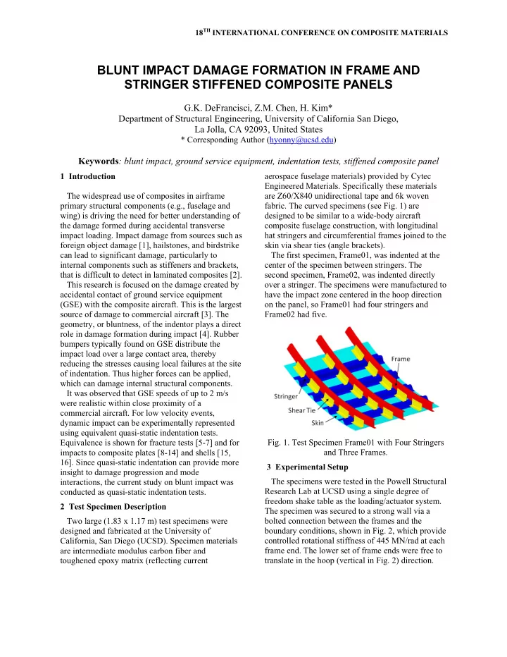
  • fabric. The curved specimens (see Fig. 1) are

designed to be similar to a wide-body aircraft composite fuselage construction, with longitudinal hat stringers and circumferential frames joined to the skin via shear ties (angle brackets). The first specimen, Frame01, was indented at the center of the specimen between stringers. The second specimen, Frame02, was indented directly

  • ver a stringer. The specimens were manufactured to

have the impact zone centered in the hoop direction

  • n the panel, so Frame01 had four stringers and

Frame02 had five.

  • Fig. 1. Test Specimen Frame01 with Four Stringers

and Three Frames. 3 Experimental Setup The specimens were tested in the Powell Structural Research Lab at UCSD using a single degree of freedom shake table as the loading/actuator system. The specimen was secured to a strong wall via a bolted connection between the frames and the boundary conditions, shown in Fig. 2, which provide controlled rotational stiffness of 445 MN/rad at each frame end. The lower set of frame ends were free to translate in the hoop (vertical in Fig. 2) direction.

BLUNT IMPACT DAMAGE FORMATION IN FRAME AND STRINGER STIFFENED COMPOSITE PANELS

G.K. DeFrancisci, Z.M. Chen, H. Kim* Department of Structural Engineering, University of California San Diego, La Jolla, CA 92093, United States

* Corresponding Author (hyonny@ucsd.edu)

Keywords: blunt impact, ground service equipment, indentation tests, stiffened composite panel

slide-2
SLIDE 2

The boundary conditions were determined using finite element analysis (FEA) by comparing the behavior of a full barrel model to a model of the smaller panel test specimen and adding rotational stiffness to the latter to achieve equivalence. Each specimen was loaded across two frames, to represent a half symmetric loading case. These specimens have been tested quasi-statically using an original equipment manufacturer (OEM) rubber cylindrical bumper mounted to a load-cell equipped fixture as shown in Fig. 3. The bumper has 178 mm and 127 mm outer and inner diameters, respectively.

  • Fig. 2. Experimental Setup of Specimen Frame01.
  • Fig. 3. Uncompressed GSE Cylindrical Bumper.

4 Results Specimen Frame01 was indented directly on the skin between two stringers. With each successive loading (referred to as Loading L1 to L4), the panel lost overall stiffness due to the development of damage, as shown in Fig. 4. During Loading L1, audible damage at a load of 28.91 kN was followed by a load drop of 1.11 kN. No visible damage was

  • bserved, however, it was deduced that the center

shear tie (ID: F01H) on Frame #2 (see Fig. 2 for IDs) experienced delamination in the radius region. This assessment was supported by back-to-back strain gage data on shear tie F01H. During Loading L2, both Frames #1 and #2 experienced rotation (due to shear-center effect on open C-shaped cross- section) at the loaded location. At 57.83 kN and 16.5 mm indentation, shear tie F01H completely failed and the center frame rebounded (less rotation of the frame), followed by a load drop of 11.12 kN. The damage to the specimen was limited to shear tie F01H broken into multiple pieces and significant damage to shear tie F01C attached to Frame #1. During Loading L3, the upper stringer contacted Frames #1 and #2, creating a direct load path to the

  • frames. The vertical location of the bumper was

designed so that the cylindrical bumper was centered between stringers upon initial contact. However, when the cylindrical bumper was fully compressed, the indentation area was more accurately defined by the steel box beam that supports the bumper (see

  • Fig. 3). During large deformations, the specimen

exhibited an overall elongation which caused a slightly eccentric loading location that is biased towards the upper stringer. The first load drop at 40.6 mm indentation (55.6 kN, load drop of 8.9 kN) was caused by a dramatic shift and increase in the rotation of Frame #2, which reduced the bending rigidity of the frame. At 53.34 mm of indentation (55.60 kN), complete full-width fracture of shear tie F01C led to a load drop of 15.12 kN. The final damage during Loading L3 was severing (fiber failure) of the stringer above the indentor due to penetration of Frame#2 through the stringer at 62.23 mm indentation (44.49 kN, with a load drop of 1.33 kN). This was immediately followed by a load drop

  • f 9.34 kN and delamination of the top stringer
  • flange. Fig. 5 shows the damage to the backside of

specimen Frame01. During the final loading sequence L4, through- thickness cracking in Frame #2 was observed where the stringer contacted the frame below the indentor. The test was stopped at an indentation of 70.59 mm (47.36 kN) in order to prevent damage to Frame #3, which was reused in the following frame specimen

slide-3
SLIDE 3

BLUNT IMPACT DAMAGE FORMATION IN FRAME AND STRINGER STIFFENED COMPOSITE PANELS

  • test. It is hypothesized that if loading had continued,

further damage to Frame #2 or damage to the lower stringer would have occurred. After Loading L4, there was no clearly exterior-visible damage to the panel except a few small cracks by the bolts on the center shear ties. The Frame01 test specimen has been modeled with FEA using shell elements as shown in Fig. 6.

  • Fig. 4 includes a comparison of the force vs.

displacement history of the experimental results from the Frame01 test with finite element model predictions for two cases: (i) a pristine specimen and (ii) one having assumed damage. As shown in Fig. 4, case (i) correlates well with the Loading L1 up until an initial failure event, at which time the two curves deviate because the finite element model does not account for any material failures. This shows that the specimen initial response can be accurately simulated with simplified modeling techniques, such as neglecting the details of the bolted connections. The shear tie to frame and shear tie to skin connections were modeled as a single laminate with the layup of both individual (bolted together) laminates combined. To extract specimen stiffness values that can be correlated to larger models (such as a full barrel model), laminated shell elements are adequate and more cost efficient. This is especially important for exploring multiple scenarios and impact locations. The complete fracture of shear ties F01H and F01C in the third loading (L3) prior to frame penetration and stringer delamination left a gap between the skin and frames. Therefore FEA case (ii) is an elastic model with the two center (damaged) shear ties manually removed. As shown in Fig. 4, the case (ii) damaged model matches very well with the experimental results after the center shear ties were broken into multiple pieces and thus did not contribute any stiffness. Therefore, if a damage mode can be assumed (such as shear tie damage), then manually removing the damaged elements gives an accurate representation of the damaged panel behavior. The pristine and damaged model then bound a panel contact/indentation stiffness range that includes some amount of intermediate damage. By defining a failure threshold force level of 50 kN, the prediction of the total energy required to generate various levels of damage, as described in Fig. 4, can be estimated. This energy can then be associated to the GSE threat (i.e., mass and velocity of GSE). Fig.4. Progressive Load vs. Displacement for Frame01.

slide-4
SLIDE 4

Fractured Shear Tie (Liberated Fragment Not Shown) Severed Stringer Delaminated Flange Frame #2 Upper Stringer

Runs Toward Frame #3

  • Fig. 5. Frame01 Inside View Showing Severed Stringer and Delaminated Flange After Loading L3.

U1

  • Fig. 6. Frame01 Pristine Elastic Finite Element Model (left) and “Damaged” Elastic

Finite Element Model at 25.4 mm Indentor Displacement. The Frame02 specimen having five stringers and three frames was indented at the specimen center directly over the stringer. The load vs. displacement plots for the two successive quasi-static loadings (referred to as Loading L1 and L2) applied to this specimen are shown in Fig. 7. During Loading L1, the skin and shear ties deformed enough to allow the stringer to make contact with the two frames directly under the indentor. This provided a direct load path from the indentor to the frames before failure of the shear ties. At a displacement of 37.25 mm (62.45 kN, with a load drop of 2.31 kN), a crack in the skin developed, centered under the stringer and

  • riginating from the edge of the panel. In addition to

the 155 mm long skin crack, there was crushing damage at the corner of the four shear ties above and below the center stringer. There was no detectable delamination between the stringers and skin using ultrasonic A-scan. During Loading L2, the contact between the center stringer and frame played a critical role in the behavior of the panel. Prior to penetration of the

slide-5
SLIDE 5

BLUNT IMPACT DAMAGE FORMATION IN FRAME AND STRINGER STIFFENED COMPOSITE PANELS

frame through the stringer, a series of small load drops occurred as the frames rotated. This rotation was constrained by the frictional forces between the contacting frames and center stringer. When the friction forces were overcome, the frame incrementally rotated more. In doing so, the bending rigidity of the frames was reduced and the panel became more compliant overall. Loading L2 caused the skin crack to grow to a length of 290 mm, measured from the free edge. At a displacement of 47.60 mm (70.95 kN) Frame #2 penetrated through the center stringer. Further penetration of Frame #2 at a displacement of 52.67 mm caused additional stringer and shear tie damage. Finally, Frame #1 ruptured just above the center stringer at a displacement of 56.33 mm and a load of 58.94 kN, as indicated in Fig. 7 and shown in Fig. 8. The damage progression during Loading L2 in specimen Frame02, as well as the observations in L3 and L4 in specimen Frame01, shows a key phenomenon to be the interaction between the contacting stringers and frames, where failures developing on either side of the contact are in competition with each other. This is dependent on the design details and layup (thickness) of the stringer and frames, as well as the amount of rotation the frames undergo which affects the geometry of the contact.

  • Fig. 7. Progressive Load vs. Displacement for Frame02.

5 Conclusions Damage caused by contact with the rubber bumper typically found on GSE can be difficult to visually

  • detect. The Frame01 test underwent significant

progressive damage with initial damage having

  • ccurred in the shear ties. Contact between the

stringer and frame provided a direct load path to the frames, even before the shear ties were completely

  • severed. Increasing frame rotation caused dramatic

load drops as the bending rigidity of the individual frames decreased. The Frame02 specimen provided a more direct load path to the frames than Frame01 because the bumper applied load directly onto the stringer-skin connection, which then directly contacts the frames. Therefore, damage to Frame02 was more dependent on the interaction between the frame and center stringer than the progressive damage developed in the shear ties. For both specimens, the amount of damage is directly proportional to the level of indentation of the skin. The experiments showed that the loads prior to full collapse of the hollow bumper are low (less than 4.45 kN) and caused no damage to the specimen. Therefore, simulating the collapse of the bumper was not necessary and the finite element models use

slide-6
SLIDE 6

a solid rubber bumper with the same dimensions as the experimentally-observed compressed bumper (i.e., flat pad with 2X wall thickness total depth). This modeling decision helped to resolve numerical instability issues associated with simulating the full process of collapsing the hollow cylindrical rubber

  • bumper. Simple, elastic, manually-degraded finite

element models using shell elements can provide valuable insight to the behavior of the test

  • specimens. This can be achieved by manually

degrading the model by removing failed components from the model. The models can be used to estimate energy absorption leading up to major failures – namely stringer and frame cracking. By clearly understanding the damage evolution process, the avenues by which one can improve blunt impact damage resistance can be identified from these results. For example, one might change the frame cross-section geometry to reduce rotation,

  • r modify the shear ties to resist crushing and

bending failure or absorb impact energy as the frames undergo large deformations. These suggestions seek to prevent frame-stringer contact which is a necessary precursor to development of major damage, i.e., stringer or frame failure.

  • Fig. 8. Frame02 Broken Frame#1 at 58.94 kN

Experiencing Significant Rotation Under Load. References

[1] G Schoeppner, S Abrate. "Delamination Threshold Loads for Low Velocity Impact on Composite Laminates." Composites: Part A. Vol. 31, No. 9. pp 903-

  • 15. 2000.

[2] S Abrate. "Impact on Composite Materials." Applied Mechanics Review. Vol. 44, No. 4. pp 155-90. 1991. [3] International Air Transportation Association." Ground Damage Prevention Programme Targets 10% Cost Reduction." Industry Times; p. Article 4. 2005. [4] C Poe, Jr." Simulated Impact Damage in a Thick Graphite/Epoxy Laminate Using Spherical Indenters." NASA TM-100539. 1988. [5] H Maikuma, JW Gillespie, Jr., DJ Wilkins. "Mode II Interlaminar Fracture of the Center Noch Flexural Specimen Under Impact Loading." Journal of Composite

  • Materials. Vol. 24, No. 2. pp 124-49. 1990.

[6] PB Crosley, EJ Ripling." Significance of Crack Arrest Toughness(Kla) Testing." Crack Arrest Methodology and Applications, ASTM STP 711; p. 301-37. 1980. [7] PLN Murthy, CC Chamis." Dynamic Stress Analysis

  • f Smooth and Noched Fiber Composite Flexural

Specimens." Composite Materials: Testing and Design (Seventh Conference): ASTM STP 893; p. 368-91. 1986. [8] W Jackson, C Poe." The Use of Impact Force as a Scale Parameter for the Impact Response of Composite Laminates." NASA TM-104189. 1992. [9] E Wu, K Shyu. "Response of Composite Laminates to Contact Loads and Relationship to Low-Velocity Impact." Journal of Composite Materials. Vol. 27, No. 15. pp 1443-64. 1993. [10] S Lee, P Zahuta. "Instrumented Impact and Static Indentation of Composites." Journal of Composite

  • Materials. Vol. 25, No. 2. pp 204-22. 1991.

[11] W Elber." Failure Mechanics in Low-Velocity Impacts on Thin Composite Plates." NASA TP-2152. 1983. [12] Y Kwon, B Sankar. "Indentation-Flexure and Low Velocity Impact Damage in Graphite Epoxy Laminates." Journal of Composite Technology and Research. Vol. 15,

  • No. 2. pp 101-11. 1993.

[13] P Sjoblom, T Hartness, T Cordell. "On Low-Velocity Impact Testing of Composite Materials." Journal of Composite Materials. Vol. 22, No. 30. pp 30-52. 1988. [14] T Tan, C Sun. "Use of Statical Indentation Laws in the Impact Analysis of Laminated Composite Plates." Journal of Applied Mechanics, Transactions of the ASME.

  • Vol. 52, No. 7. pp 6-12. 1985.

[15] B Wardle, PA Lagace. "On the Use of Quasi-Static Testing to Assess Impact Damage Resistance of Composite Shell Structures." Mechanics of Advanced Materials and Structures. Vol. 5, No. 1. pp 103-21. 1998. [16] PI Meyer. "Low-Velocity Hard-Object Impact of a Filament-Wound Kevlar/Epoxy Composite." Composite Science and Technology. Vol. 33, No. 4. pp 279-93. 1988.