
SLIDE 1
C C GAS SYSTEMS, LLC 50 MMBTU Hazardous Waste Incinerator GENERAL - - PowerPoint PPT Presentation
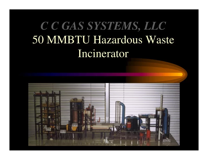
C C GAS SYSTEMS, LLC 50 MMBTU Hazardous Waste Incinerator GENERAL OVERVIEW The plant consists of the following items supplied by ,C C GAS SYSTEMS, LLC Tank farm consisting of five (5) each high BTU storage tanks c/w steam coils and
and five (5) each low BTU storage tanks w/o steam coils. In addition to the above tanks, future expansion has been allowed for four (4) more tanks, two (2) high BTU and two (2) low BTU tanks.
system consisting of a condenser to collect the gases as a liquid and return them to the feed stream and a charcoal absorber to scrub the gases prior to releasing them to the atmosphere.
afterburner, flue gas cooler, spray dryer, baghouses, quench tower, cyclone separator, I.D. fan, exhaust stack and control unit.
purchased at additional cost! (i.e.: desalination plant)
PUMPS :
LOW BTU WASTE
NITROGEN 45 PSIG CONDENSER CHARCOL ABSORBER TO ATMOSPERE
HIGH BTU WASTE
c/w STEAM COILS
FUTURE EXISTING
DUST SUPPRESSION SPRAY SOLID FEED HOPPER SHREDDER NITROGEN PURGE CARBON DIOXIDE PURGE DOUBLE AIR LOCK VALVES
RAMLUGGER BUCKET SCREW FEED AUGAR BULK RECEIVING HOPPER SEAL GATE VALVE DRUM FEED
Transition Section & Ash Hopper Rotary Kiln (First Stage) 900 to 1800 F (-1/4" to -1/2" W .C.) (Residence time 27.3 to 273 min.) (1.3% slope) (0.2 to 2.0 RPM) Stationary Second Stage 1900 to 2400 F (Residence time 2 sec. min.) High and Low BTU Liquid W aste from Storage & Natural Gas for Pilot/Burner FEED TO ROTARY KILN FROM BULK FEED SYSTEM Relief Vent To Flue Gas Cooler
R A D I E N T S E C T I O N Q U E N C H T O W E R
FROM AFTERBURNERTO SPRAY DRYER H2O STEAM DRUM CONVECTION SECTION 3 DRUM UNIT
S p ra y Dryer & A sh C ollector 6 50 to 3 50 F
FR O M C O N V E C T IO N SE C TIO N C A U ST IC S O D A TO B A G H O U SE (S )
Bag House Bag House HCL & S02 Monitor Bag House Bag House FROM SPRAY DRYER TO QUENCH TOWER
ID Fan E x h a u s t Wet Scrubber (Free Jet) (Cyclonic Separator) Quench Tower 350 to 160 F CAUSTIC SODA
The plant was designed to handle five (5) categories of waste streams:
modifications)