SLIDE 1
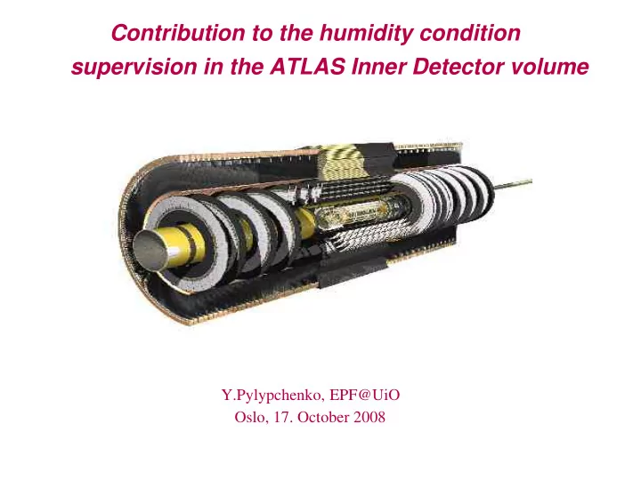
Contribution to the humidity condition supervision in the ATLAS Inner Detector volume
Y.Pylypchenko, EPF@UiO Oslo, 17. October 2008
SLIDE 2 Overview
➲ Dew point monitor in the exhaust of the N2 volume
- Design
- Installation
- Readout and DCS software
- Commissioning
➲ Humidity measurements in the ATLAS ID general volume
- Classification and Cataloging
- HMX2200 relative humidity sensors
- Monitoring
SLIDE 3 N2 exhaust Dew Point Monitor
➲ Purpose
To x-check the environmental conditions in Pixel, SCT Barrel and SCT End-cap volumes Using vradiation hard relative humidity (RH) and temperature (T) senors Interfaced with a SIEMENS Simatic S7-300 PLC that takes care
- f signal processing and sending the processed data to PVSS
➲ General layout
Sensors are placed in the UX15 detector cavern at the N2 exhaust Conditioning board and PLC are placed in the USA15 controlled area
SLIDE 4 RH, T and Dew Point
➲
Having RH and T measurement
➲
To calculate Dew Point temperature Td we model of the saturation vapor pressure dependence upon the temperature is needed
➲
We relay on a simple parametrization whose coefficients are computed by fitting the data
324.175 17.08085 6.10780
Water 245.425 17.84362 6.10780
Water 272.440 22.44294 6.10714
Ice
C3 [oC] C2 [ - ] C1 [ mbar]
T [oC] Phase
RH basics:
✗
RH is the ratio between the actual partial vapor pressure Pv and the satura- tion vapor pressure above water (ice) Ps
✗
“Dew (Frost) Point temperature Td” it is when Ps(Td)=Pv(Td) and condensation begins:
✗
Decreasing the temperature below the Dew Point temperature the partial vapor pressure exceeds the saturation value, so condensation occurs until the bal- ance is reached again.
SLIDE 5
Inner Detector Volume
The inner ATLAS tracker (SCT and Pixel detector) will be cooled down to temperatures of -20oC. To prevent creation of ice the frost point in the environmental gas needs to be below -30oC.
SLIDE 6
N2 system
➲
N2 system: Four manual gas circuits, each of them supplies gas to Pixel, SCT endcap A, SCT endcap C and SCT barrel.
➲
Nitrogen flushed through the inner part of the ID (SCT + Pixel) ensures the dry envi- ronmental condition inside the Thermal Enclosure
SLIDE 7
N2 system exhaust
N2 exhaust racks in UX15 cavern at level1 Y.59-04.X1 (left) & at level 7 Y.62-04.X7 (right)
SLIDE 8 Operational conditions
➲
Requirement for the humidity sensor
- 1% resolution over a large relative humidity range
- especially functional in the low (0-20 %) range
- perational at subzero temperatures
- radiation hard
- with an option to read the sensor with conditioning electronics posi-
tioned at a distance of about 100 m
A wide array of humidity measurement instrumentation is available due to the importance of humidity control and monitoring in nu- merous industries. However, very few are operable under the ex- treme conditions expected.
SLIDE 9 Humidity sensor
➲
Choice: HMX2200 by Hygrometrix Inc
➲
MEMS* piezoresistive strain gauge tech- nology sensor + 8Kbit EEPROM** in a single package
➲
proved to be quite robust
➲
while for relatively low cost (due to using semiconductor fabrication techniques)
➲
radiation hard
➲
and the performance suited the needs
➲
provides the T measurement in addition Navigated by:
CMS note “The humidity sensors for the CMS Tracker”, sensor characteristics provided by the production company Conditioning circuit that translates the sensor output to a 4-20 mA current (in- dustrial standard) developed in Genova
*MEMS stands for micro-electromechanical system **EEPROM = electrically erasable programmable read-only memory
SLIDE 10 HMX calibration in Genova
Measurement on confined volume of gas:
➲
Sensor enclosed in a box
➲
which collects the gas
➲
and cools it down to the required by precision temperature
➲
Peltier element introduced for cooling purposes
➲
Tests and development in Geno- va
➲
with the target of 20 l/min at the exhaust
SLIDE 11
Power Cables
➲
Presence of the cooling elements required additional power cables...
Thanks a lot to Ole Røhne & Bjørn Samset for the help with moving that heavy stuff around!!!
SLIDE 12 Sensors setup in UX15
➲
Fife “boxes” installed at the end of N2 ex- haust pipes
➲
Thermally isolated“Box”
- hosts HMX and Pt1000 sensors
- equipped with Peltier cooling elements
to cool the incoming gas to the required temperature of about -4 o C
- electro-valves at the inlet and outlet to
control gas flow
- AC fan (ouside of the box) for removing
the heat
➔
required to equip the N2 exhaust racks with 230 AC V power lines
SLIDE 13 Setup in USA15
Rack Y.30-21.A1
➲
HMX conditioning board
➲
7 additional PS (SIEMENS SITOP Flexi)
- for 5 Peltier coolers, electro-valves and conditioning
board.
➲
PLC rail with
- PS, CPU, CP, 2 AI for HMX, 1 AI for Pt1000, 1 DO
module for releys
➲
PLC software:
- Converts the voltages to T, RH and Dew Point for each mea-
suring point
- Controls the electro-valves
➲
PLC is connected to the LCS via Ethernet (IP/TCP)
➲
Due to specific conditions of ATN PLC can be programmed only with the direct PC connection with PLC USB adapter (EPF property). PC should have STEP7 software installed
➲
Required to arrange additional 230 VC V power lines to the rack for the installed equipment It would be impossible without Giovanni, Ettore and Alessandro from Genova as well as W.Iwanski assistance
SLIDE 14 Installation and Post-installation
➲
The system was installed in March 2008
➲
Right after installation and connection it was realized that at the present N2 flow it will not function as planned
➲
in April 2008 valves were taken out, input pipe diameter increased
➲
turning to the measurement on the gas continuous flow (instead that on confined volume
➲
The flow (~20 l/h) is enough, nevertheless, to measure low dew point
SLIDE 15 Local Test Setup
➲
To enhance the software development
- ELMB + ELMB Mother board
- NTC and HIH-400 sensors
- Kvaser LapCAN
- HP Laptop runnign Windows XP with installed
PVSS
SLIDE 16
DCS software: PVSS part
➲
5 datapoints with 5 DPE in each representing T, RH, DP, VRH, VT
➲
Connected to the PLC with Native Simatic S7 driver (part of PVSS)
➲
Pulling mode is used; pulling time 5 sec
➲
T, RH and DP values are archived with smoothing
SLIDE 17 DCS soft: FSM hierarchy
➲
Part of the IDEENV FSM (still under development)
- Provides the information to the IDECOOL
SLIDE 18
Magnetic Ventilation
➲
During magnet tests in July'08 it was observed another drawback of the system: AC fans meant to dissipate heat from the Peltier do not tolerate the Toroidal field.
SLIDE 19
Magnetic Ventilation
➲
Solution: use compressed air instead of any fans to ensure air ventilation in the N2 exhaust racks
➲
Would not make it without help of Alex Bitadze, Koichi Nagai and Valery Akhnazarov.
SLIDE 20 Summary on N2 exhaust Dew Point monitor
➲
Commissioning is ongoing, sensor signals look very stable (monitoring basically ch1 performance)
- Despite of the luck of the N2 flow made the system provides rea-
sonavle insight to the env. conditions inside thermal enclosure
- Calibration looks OK . Good correlation with the values from in-
side the SCT
- Ch4 extensively used by Pixel community as a benchmark
➲
Work on updating the IDEENV FSM tree with dedicated N2 exhaust monitor panels
➲
Some attempts to create documentation in form of EDMS note
SLIDE 21
RH in the ID global volume
➲
Catalog of all RH sensors in the Pixel, SCT and ID global volumes
➲
Localize the position of the sensors in the ID global
➲
PVSS panel summarizing all RH measurement
➲
Summary page on ATLAS ID Twiki (https://twiki.cern.ch/twiki/bin/view/Atlas/IDHumiditySensors)
SLIDE 22
RH in the ID global volume
➲
PVSS panel to summarize all RH measurement in the ID (except TRT)
➲
Split to three panels (buttons) in the IDEENV
SLIDE 23 New RH in the ID global volume
➲
Packages with HMX2200 and NTCs installed at the far heaters
➲
HMX signals conditioned with Genova boards are interfaces with the PLC
- additional two AI modules were installed for this purpose in July 2008
- wiring and re-programming PLC to include newcomers
➲
NTC are not connected ---> both RH and T from the same HMX
➲
Added to the IDEENV
➢
Second order poly- nomial used to com- pute RH as a func- tion of T and Vout
➢
Polynomial coeffi- cients obtaned from fitting the calibra- tion data provided by supplier
SLIDE 24
Summary
➲
N2 dew point monitoring system designed, installed and nearly commis- sioned
➲
RH sensors in the ID volume are cataloged and their performance is un- der control
➲
Permanent monitoring of the RH and Dew Point in the ID volume
SLIDE 25
Summary
➲
N2 dew point monitoring system designed, installed and nearly commis- sioned
➲
RH sensors in the ID volume are cataloged and their performance is un- der control
➲
Permanent monitoring of the RH and Dew Point in the ID volume
➲
Calibration for new HMX should be x-checked
➲
Possible NTC measurement recovered by using IDEENV ELMB channels
➲
EDMS not on the new HMX connection and calibration
SLIDE 26
At the end...
➲
During the process of installation and commissioning this place became like a second home :) Thanks to Ole, Katarina and Lillian for lending cameras