D IVIDE AND C ONQUER : Partitioning OSPF networks with SDN Marcel - - PDF document

d ivide and c onquer partitioning ospf networks with sdn
SMART_READER_LITE
LIVE PREVIEW

D IVIDE AND C ONQUER : Partitioning OSPF networks with SDN Marcel - - PDF document

D IVIDE AND C ONQUER : Partitioning OSPF networks with SDN Marcel Caria, Tamal Das, and Admela Jukan Marco Hoffmann Technische Universit at Carolo-Wilhelmina zu Braunschweig NOKIA Email: { m . caria, t . das, a . jukan } @tu-bs . de marco .


slide-1
SLIDE 1

DIVIDE AND CONQUER: Partitioning OSPF networks with SDN

Marcel Caria, Tamal Das, and Admela Jukan

Technische Universit¨ at Carolo-Wilhelmina zu Braunschweig Email: {m.caria, t.das, a.jukan} @tu-bs.de

Marco Hoffmann

NOKIA marco.hoffmann@nsn.com

Abstract—Software Defined Networking (SDN) is an emerging network control paradigm focused on logical centralization and programmability. At the same time, distributed routing protocols, most notably OSPF and IS-IS, are still prevalent in IP networks, as they provide shortest path routing, fast topologi- cal convergence after network failures, and, perhaps most importantly, the confidence based on decades

  • f reliable operation. Therefore, a hybrid SDN/OSPF
  • peration remains a desirable proposition. In this

paper, we propose a new method of hybrid SDN/OSPF

  • peration. Our method is different from other hybrid

approaches, as it uses SDN nodes to partition an OSPF domain into sub-domains thereby achieving the traffic engineering capabilities comparable to full SDN operation. We place SDN-enabled routers as sub- domain border nodes, while the operation of the OSPF protocol continues unaffected. In this way, the SDN controller can tune routing protocol updates for traf- fic engineering purposes before they are flooded into sub-domains. While local routing inside sub-domains remains stable at all times, inter-sub-domain routes can be optimized by determining the routes in each traversed sub-domain. As the majority of traffic in non-trivial topologies has to traverse multiple sub- domains, our simulation results confirm that a few SDN nodes allow traffic engineering up to a degree that renders full SDN deployment unnecessary.

  • I. INTRODUCTION

Distributed IP routing protocols, like OSPF or IS-IS, have worked consistently and predictably in the cur- rent Internet and have proven their reliable operation

  • ver time. Software Defined Networking (SDN), on the
  • ther hand, is a new networking paradigm based on a

logically centralized and programmable control plane, that has gained a lot of attention recently. In fact, most network equipment vendors have announced the intention to build devices that support the OpenFlow protocol, the de facto SDN messaging standard, or have already released OpenFlow-capable products [1]. Migrating to a fully SDN-enabled operation is how- ever not without issues and new costly investments. In fact, ISPs are still reluctant regarding the change

  • f the control plane paradigm in their networks from

distributed to centralized, as distributed routing pro- tocols operate consistently and predictably over years, efficiently control real life conditions, and reliably re-
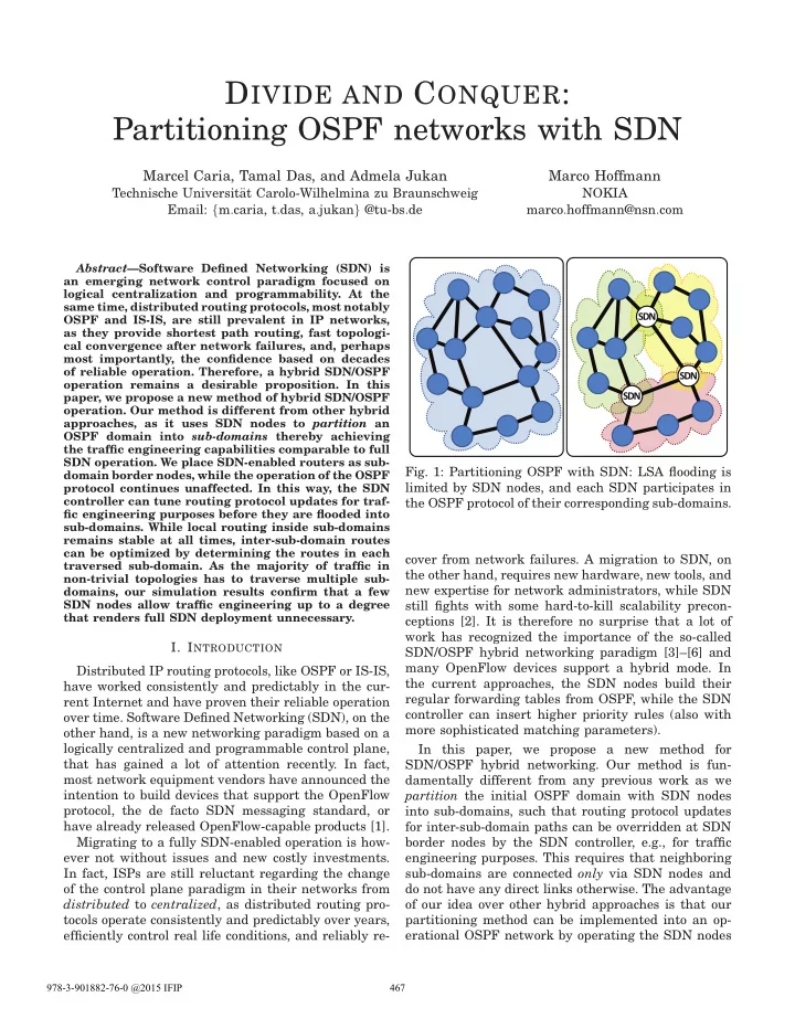
N S D N S D N S D

  • Fig. 1: Partitioning OSPF with SDN: LSA flooding is

limited by SDN nodes, and each SDN participates in the OSPF protocol of their corresponding sub-domains. cover from network failures. A migration to SDN, on the other hand, requires new hardware, new tools, and new expertise for network administrators, while SDN still fights with some hard-to-kill scalability precon- ceptions [2]. It is therefore no surprise that a lot of work has recognized the importance of the so-called SDN/OSPF hybrid networking paradigm [3]–[6] and many OpenFlow devices support a hybrid mode. In the current approaches, the SDN nodes build their regular forwarding tables from OSPF, while the SDN controller can insert higher priority rules (also with more sophisticated matching parameters). In this paper, we propose a new method for SDN/OSPF hybrid networking. Our method is fun- damentally different from any previous work as we partition the initial OSPF domain with SDN nodes into sub-domains, such that routing protocol updates for inter-sub-domain paths can be overridden at SDN border nodes by the SDN controller, e.g., for traffic engineering purposes. This requires that neighboring sub-domains are connected only via SDN nodes and do not have any direct links otherwise. The advantage

  • f our idea over other hybrid approaches is that our

partitioning method can be implemented into an op- erational OSPF network by operating the SDN nodes

978-3-901882-76-0 @2015 IFIP 467

slide-2
SLIDE 2

initially (i.e., during the migration) in plain OSPF

  • mode. It follows that the SDN nodes in our scheme

belong to all sub-domains to which they are connected. Figure 1 illustrates the idea. When all sub-domain border nodes are replaced with SDN-enabled devices and an optimized routing has been determined, the SDN nodes start the update process in the individual sub-domains by flooding routing updates that are in- dividually tuned per sub-domain. Our method capital- izes on the advantages of distributed routing protocols by letting the routing inside each sub-domain be based

  • n OSPF solely so that it remains unchanged and

stable at all times. At the same time, inter-sub-domain routes can be optimized by determining the routes in each traversed sub-domain. As the majority of traffic in non-trivial topologies has to traverse multiple sub- domains, our simulation results confirm that a few SDN nodes allow traffic engineering up to a degree that renders the full SDN deployment unnecessary. The rest of the paper is organized as follows: Sec- tion II discusses the related work and Section III presents the network architecture. The mathematical model of the traffic engineering logic is presented in Section IV. Section V presents the performance study and Section VI the conclusions.

  • II. RELATED WORK

Our method appears similar to the partitioning of an OSPF domain into so-called OSPF areas [7], how- ever the use is different, as OSPF areas are used to simplify the administration of large topologies and to reduce the amount of protocol traffic. Our intention is also different, as we partition the OSPF domain to allow SDN-based traffic engineering by controlling the routes of inter-sub-domain traffic. The SDN/OSPF hybrid networking paradigm has been previously analyzed and explained to a great deal in [3]–[6]. For the capability of the SDN controller to insert higher priority rules into the forwarding tables, this has also been coined as ”policy based routing on steroids” [8]. The ”topology-based hybrid SDN model” by Vissicchio et al. in [9] differs from the other ap- proaches in this respect, and is interesting to us, as it partitions the network into zones, whereby each node belongs to one zone only. However, the zone approach is different from our concept of sub-domains, as a zone is defined as a set of interconnected nodes controlled by the same paradigm (i.e., SDN or OSPF). In contrary, a sub-domain in our approach is a subgraph of OSPF routers, while the SDN nodes participate in the OSPF. There are other architectural solutions for traffic engineering (TE), most prominently MPLS. However, we argue that unlike our method, MPLS requires a full deployment in the entire topology and it adds another architectural layer to the network (including its overhead in the data plane). Only a full migration to SDN would actually provide equal performance in terms of TE. Both solutions however, i.e., MPLS and SDN, assume the previously mentioned change to the centralized control plane paradigm. In contrast to these solutions, our method relies mainly on OSPF, while optimized routes are injected into the regular protocol operation by individually tuned routing pro- tocol updates. Our results also show that our method requires relatively few SDN nodes to achieve the same traffic engineering capability to the one with the full MPLS or SDN deployment. Finally, an intuitively similar approach would be to partition the initial OSPF domain and connect the sub-domains with BGP, while BGP can then be used for load balancing, like shown in [10]. The degree of freedom here regarding routing optimizations are in fact similar to what our method can offer. However, our method does not require the partitioning of the initial routing domain into multiple autonomous systems and provides a clean separation from the BGP setup that

  • perative WANs have already in place.
  • III. NETWORK MANAGEMENT ARCHITECTURE

We propose an SDN/OSPF hybrid network manage- ment subsystem, with a TE scheme applicable to a sin- gle OSPF routing domain. A routing update is referred to as Link State Advertisement (LSA) and an OSPF router participating in the protocol distributes all its topological information by flooding LSAs throughout the entire network. Figure 2 depicts the assumed Layer 3 network management architecture. As it can be seen, the actual network includes both OSPF and SDN routers. The SDN nodes are connected to the SDN controller and the proposed network manage- ment subsystem, referred to as Hybrid Network Man- ager (HNM), uses the controller’s northbound API. As

  • ur partitioning-based method requires some sort of

all-knowing centralized control intelligence, we con- sider the implementation as a sort of network applica- tion on top of the SDN controller. Because the OSPF protocol advertisements are essential here, the used SDN controller must be configurable to simply forward (without any processing) all LSAs received by the SDN nodes to the HNM, as well as to simply forward the LSAs generated by the HNM to the SDN nodes. 1) Hybrid Network Manager: To gather all the data relevant to Traffic Engineering (i.e., topology, SDN node placement, traffic, and routing), we assume that the HNM implements a Network Information Access Interface that has comprehensive access to various functions and data in the OpenFlow controller, and preprocesses and does the re-formating of this data for the TE Engine, as well as it extracts the rout- ing information from the received LSAs. The Traffic Engineering Engine (depicted as ”TE Engine” block in Figure 2) is our main module inside the HNM, which

2015 IFIP/IEEE International Symposium on Integrated Network Management (IM2015) 468

slide-3
SLIDE 3

T A

authentic LSA tuned LSA

Hybrid Network Manager

  • Netw. Inform.

Access Interf.

Topology Traffic OSPF Routing SDN Routing

OSPF

TE Engine

HNM

Controller Platform Northbound APIs (Rest) Protocol Plugins Network Applications

Other Apps

Partitioning Logic Load Balancer LSA Generator OpenFlow SNMP Netflow

  • ther protocols

OpenFlow Controller

Data Instructions Data Instr.

N S D N S D N S D

T A T A

  • Fig. 2: The network architecture proposed

is used to determine the optimum routing based on the provided data. This module is aware of the OSPF topology partitioning, optimizes the inter-sub-domain routing for load balancing, and computes the according (tuned) OSPF link metrics that will be flooded as LSAs into the individual sub-domains. The TE Engine then passes on the computed routes to the SDN controller’s Controller Platform (shown inside the OpenFlow con- troller) and forwards the LSAs to the corresponding SDN routers. 2) SDN Integration into an OSPF network: Let us assume a single domain and single area OSPF net-

  • work. Assuming that a few OSPF routers have been

replaced by the SDN-enabled devices, the first step for integration into an OSPF networks is to configure the SDN nodes to operate autonomously in the OSPF

  • mode. When the proposed control and management

architecture is fully deployed (i.e., the HNM is oper- ating on top of the SDN controller), the sub-domain border nodes can be switched over to SDN mode. From this time on, the SDN nodes send the authentic LSAs (depicted as the black packets marked with an A) received from their OSPF neighbors to the HNM, where they are processed. During the following initial- ization phase, the HNM is not altering any routing and replies with LSAs according to regular OSPF

  • peration. This phase is used by the HNM to gather

all required topology and routing information from the SDN controller and the LSAs received from the OSPF

  • routers. This also involves the logical partitioning of

the single OSPF domain into sub-domains depending

  • n the SDN node placement. When the initialization

phase is completed (i.e., when the HNM has all data available), the HNM switches over to the load balanc- ing (or, TE) phase, in which it computes the optimum routes that are then translated into link metrics for the tuned LSAs (depicted as the red packets marked with a T). The HNM computes LSAs for load balancing individually depending on the sub-domain and the advertising border node. It then forwards these LSAs via the OpenFlow channel to the corresponding SDN nodes, which distribute them in the corresponding sub- domain via flooding. 3) SDN Node Placement: To enable the separation

  • f the OSPF domain into distinct sub-domains, a

few SDN-enabled routers must be placed in strategic positions in the network, such that their removal partitions the topology into disconnected components. Obviously, the way the network is clustered into sub- domains is determined solely by the operator’s choice

  • f nodes that will be exchanged with SDN nodes,

i.e., the sub-domains are determined only once in the beginning and can be changed only by adding new

  • r changing the position of existing SDN nodes. In

graph theory parlance, this means that the SDN- enabled routers must constitute one or multiple vertex

  • separators. An example of how to partition a topology

is shown in Figure 1, where it can be seen that the removal of any two SDN nodes separates the topology into two disconnected subgraphs. Evidently, the SDN- enabled nodes have to be placed at the weak points

  • f the topology from a network reliability perspective.

However, it is one of the strengths of our hybrid scheme that in case of a failing sub-domain border node, OSPF takes care of finding alternative paths via

  • ther border nodes. We control the routing of inter-

sub-domain flows only by determining which border node is preferred over the others (by the advertised link metrics), and in case that preferred node fails, the next least cost route via a different border node is automatically used. It should be noted that the partitioning we use in this paper is rather simplistic: For a given number

  • f SDN-enabled routers, we chose those nodes to be

replaced that result in the partitioning with the max- imum number of inter-sub-domain flows in the net-

  • work. Better partitioning strategies are in fact likely

to yield better results (outside the scope here). 4) LSA Tuning: The partitioning of the OSPF area allows to advertise routing updates customized per sub-domain, which in turn enables to control the routing of traffic flows between the sub-domains. It should be noted that the OSPF routing of sub-domain- internal traffic is not affected at all. Figure 3 depicts how LSA altering can be used to change the routing: The first sub-figure shows the original OSPF network and how the two SDN-enabled nodes x and y are used to partition the domain into two distinct sub- domains (containing the nodes {a, b, x, y} in the here considered sub-domain, in which we observe the rout- ing changes, and nodes {c, d, x, y} in the other sub- domain respectively). The second sub-figure shows how paths can be controlled, when only the sub-domain-

2015 IFIP/IEEE International Symposium on Integrated Network Management (IM2015) 469

slide-4
SLIDE 4

a x c b y d

considered sub-Domain

c d c d

100 100 500 500 97 100 100 100 100 100 100 100

a x b y

considered sub-Domain

100 100 100

a x b y

considered sub-Domain

100 100 100

  • riginal link metric

tuned link metric IP link added (logical) IP link OSPF node SDN node

x b

1) Original OSPF Network 2) Altered Link Metrics 3) Altered Topology

102

  • Fig. 3: Altering the advertised routing information

external link metrics are altered (e.g., by changing them to the red numbers) before LSAs are flooded into the considered sub-domain. The third sub-figure shows the more powerful control method, where even the advertised topology is altered (i.e., new logical links can be advertised or existing links can be hidden). The corresponding routing paths for inter-sub-domain flows are shown in Table I, grouped in blocks according to the used LSA modification. It can be seen in Table I that by altering the link metrics in the LSAs before being flooded to nodes a and b according to the way depicted in second sub- figure of Figure 3, flows a → d and b → c change their routes so that the link between a and b is relieved and the load on the link between c and d increases

  • instead. This poses just a slight modification, which

might come in handy when link a − b is overloaded while link c − d provides enough spare capacity. The third sub-figure of Figure 3 shows the possible routing changes, when even topology information is altered in the flooded LSAs: by advertising the non-existing links y − c and x − d, both with low link metrics, all traffic for c exits the upper sub-domain via node y and all traffic for d exits via x (like shown in the third block in Table I), which wouldn’t be possible only by altering link metrics of existing links.

  • IV. LOAD BALANCER MODEL FOR TE

We now present the Integer Linear Programming (ILP) model used for the load balancer in our TE

  • engine. All parameters and variables used are listed in

Table II. We assume that all OSPF paths inside sub- domains (including their accumulated link metrics) are constant and known. It should be noted that the novelty of the routing scheme in our model requires newly defined constraints on routing which makes the model rather unique and challenging: While OSPF paths must be alternated with SDN links, SDN links

LSAs Traffic Flow Routing Path Original a→c a − x − c a→d a − b − y − d b→c b − a − x − c b→d b − y − d a→c a − x − c Altered a→d a − x − c − d Link Metrics b→c b − y − d − c b→d b − y − d a→c a − b − y − d − c Altered a→d a − x − c − d Topology b→c b − y − d − c b→d b − a − x − c − d

TABLE I: Routing of inter-sub-domain flows in Fig- ure 3 depending on the advertised routing information alone can be concatenated arbitrarily, like shown in the flowchart of Figure 4. The routing constraints: A valid routing path according to our method is a combination of OSPF paths and SDN links, see the flowchart of Figure 4. Note that our notion of the terms OSPF path and SDN link differs from the intuitive usage. We define an SDN link as a directional link between two nodes, whereas the source of the link has to be an SDN node and the destination of the link can be any (SDN

  • r OSPF) neighboring node. An OSPF path, on the
  • ther hand, is defined as the unique least cost path

(whereby the mechanisms like Equal Cost Multi Path are not considered) between a (non-SDN) OSPF node and any other (SDN or OSPF) node within the same sub-domain, which also does not traverse any SDN link (like defined previously). To illustrate this defi- nition: the directional link from an SDN node to any

  • f its neighbors can be used as an SDN link, while the

same can not be part of any OSPF path. Figure 4 shows an example network with the routing scheme proposed. The source node S has exactly one least cost path to each SDN border node (X and Y ) in Sub-Domain 1. Thus, the route from S to D starts either with OSPF path P1 or P2, depending on the cost metric for the routing to D advertised by X and Y . The next element in the route to D is an SDN

  • link. As an SDN node’s flow table can be arbitrarily

configured, e.g., for packets matching source addresses

  • f traffic from S and destination addresses of traffic

to D, we see that P1 can be continued with SDN links L1, L2 or L3. In fact, P1 can be continued even with SDN links L1 and L4 successively, whereby we’d like to note the self loop of the SDN link box in the flowchart: Because forwarding in SDN nodes is arbitrarily configurable and not constraint by OSPF, SDN links can be concatenated arbitrarily. Arriving at any of the two first OSPF nodes (node a or node b) in Sub-Domain 2, we have no choice for the next element

2015 IFIP/IEEE International Symposium on Integrated Network Management (IM2015) 470

slide-5
SLIDE 5

Destination OSPF Path SDN Link Source L1

a b D S c

P1 P2 P3 P4 P5 L2

Sub-Domain 1 Sub-Domain 2 Sub-Domain 3

SDN Node

L2 P3

OSPF Sub-Domain OSPF Node SDN Link OSPF Path

Flowchart Routing Scheme Y X Z

  • Fig. 4: Constraints on routing

Parameter Meaning N set of all nodes L ⊇ Lsdn set of all links / all SDN links SD set of all OSPF sub-domains P set of all OSPF paths (like defined) F ⊇ ˜ F set of all traffic flows / all traffic flows crossing sub-domain borders Y set of linear cost functions λf traffic demand of flow f src(x, n) binary: 1 if node n is the source of entity x (which can be a link, a path,

  • r a flow), and 0 otherwise

dst(x, n) binary: 1 if node n is the destination of entity x, and 0 otherwise tr(p, ℓ) binary: 1 if OSPF path p traverses link ℓ, and 0 otherwise Cℓ capacity of link ℓ uℓ utilization of link ℓ caused by all intra-sub-domain flows traversing ℓ ℓsa(k, p) binary: 1 if the advertisement of link metrics according to LSA set k allows usage of path p, and 0 otherwise bel(k, α) binary: 1 if the LSA set k belongs to sub-domain α, and 0 otherwise Variable Meaning Rx(f) binary: 1 if OSPF path or SDN link x is used for flow f, and 0 otherwise LSAk(d) binary: 1 if LSA set k is advertised for destination d, and 0 otherwise Uℓ utilization of link ℓ Costℓ utilization cost of link ℓ

TABLE II: Summary of Notation to add to our route to the destination, because each of the two nodes has only a single OSPF path to border node Z. Finally, Z can then be configured to forward the packets directly via link L6 to D, or in case of congestion on that link, forward the packets via L5 to OSPF node c, from where the packets have to take the OSPF path to the destination. To assure in our ILP model that there is a valid routing path for each flow, we first require that exactly

  • ne forwarding entity (i.e., an OSPF path or an SDN

link), which connects to the source node of the said flow, is used. In other words, routing has to start at the source of the flow: ∀f ∈ ˜ F, ∀n ∈ N with src(f, n) = 1 :

  • p∈P

src(p, n) · Rp(f) +

  • ℓ∈Lsdn

src(ℓ, n) · Rℓ(f) = 1 We require the same for the end of the routing path, i.e., routing has to end at the destination of the flow: ∀f ∈ ˜ F, ∀n ∈ N with dst(f, n) = 1 :

  • p∈P

dst(p, n) · Rp(f) +

  • ℓ∈Lsdn

dst(ℓ, n) · Rℓ(f) = 1 Common routing models require only a single routing continuity constraint, but like shown in the flowchart

  • f Figure 4, our model allows two different entities

for routing (shown as the intermediate states OSPF path and SDN link). Thus our model requires two different routing continuity constraints for inter- mediate nodes n. First, we demand that the usage of an OSPF path for the routing of a certain flow always requires the subsequent usage of an SDN link (or the node at the end of that OSPF path is already the destination of the said flow): ∀f ∈ ˜ F, ∀p ∈ P, ∀n ∈ N with dst(p, n) = 1 : Rp(f) − dst(f, n) =

  • ℓ∈Lsdn

Rℓ(f) · src(ℓ, n) Likewise, we demand that the usage of an SDN link for the routing of a certain flow always requires the subsequent usage of another SDN link or alternatively an OSPF path, unless the node at the end of the initial SDN link is already the destination of the said flow: ∀f ∈ ˜ F, ∀ℓ ∈ Lsdn, ∀n ∈ N with dst(ℓ, n) = 1 : Rℓ(f) − dst(f, n) =

  • m∈Lsdn

Rm(f) · src(m, n) +

  • p∈P

Rp(f) · src(p, n) The routing continuity constraints so far may appear to provide a valid routing, however, they do not prevent routing loops like shown in Figure 5. (Please note that it is not distinguished between the two entities OSPF path and SDN link in Figure 5, as the described problem is of general nature when routing continuity is modeled in ILPs.) While the only valid path from

2015 IFIP/IEEE International Symposium on Integrated Network Management (IM2015) 471

slide-6
SLIDE 6

S 1 2 3 4 D

  • Fig. 5: Routing loop

S to D is obviously S→1→2→3→D, the inconsistent routing shown as red dotted arrows is conform to all routing continuity constraints so far: Routing starts at the source (S→), at every intermediate node where routing leads to, there is a subsequent node unless we reach the destination (→1→, →2→ and →4→), and the destination is reached (→ D). The solution is to demand that for each flow, any intermediate node can be traversed at most once, which we model with the following constraint: ∀f ∈ ˜ F, ∀n ∈ N with src(f, n) = dst(f, n) = 0 :

  • ℓ∈Lsdn

Rℓ(f) ·

  • src(ℓ, n) + dst(ℓ, n)
  • +
  • p∈P

Rp(f) ·

  • src(p, n) + dst(p, n)
  • ≤ 2

This assures that the intermediate node n, if used for flow f, has not more than two routing entities of f in sum that enter and exit the node. Additionally, we need to demand that the source and destination nodes never appear as intermediate nodes along the routing path to avoid loops containing source or destination: ∀f ∈ ˜ F, ∀s, d ∈ N with src(f, s) = dst(f, d) = 1 :

  • ℓ∈Lsdn

Rℓ(f) ·

  • dst(ℓ, s) + src(ℓ, d)
  • +
  • p∈P

Rp(f) ·

  • dst(p, s) + src(p, d)
  • = 0

Finally, we need to constrain that routing through SDN border nodes has to be consistent with the ad- vertised link metrics. This means that for a given sub-domain α and for a given sub-domain-external destination node d, we require the usage of a set of link metrics (to be advertised by the SDN nodes in sub-domain α) which is consistent with all used OSPF paths from any sub-domain-internal source node to that destination d: ∀p ∈ P, ∀f ∈ ˜ F, ∀d ∈ N with dst(f, d) = 1 : Rp(f) ≤

  • k

LSAk(d) · ℓsa(k, p) With this constraint we assure that OSPF path p is used to route flow f only if the usage is consistent with the advertised set of LSAs for the destination of

  • f. Finally, as we demand that only a single set of

LSAs per sub-domain is advertised per sub-domain- external destination, we also constrain that ∀d ∈ N, ∀α ∈ SD :

  • k

LSAk(d) · bel(k, α) = 1 The lsa and bel parameters used in the last two con- straints are entirely pre-computed, and determining all valid combinations of OSPF paths for which there has to exist a distinct set of link metrics is computa- tionally complex. In our first ILP model, we had the link metrics advertised by SDN nodes for every sin- gle destination as variables, which is straightforward. This, however, turned out to be computationally too expensive even for small network sizes. For space rea- sons, we can not explain the algorithm that generates the used lsa parameter, but assume here that it is computed efficiently and is available in the model. Load balancing as objective function: The purpose

  • f the used Traffic Engineering scheme is to load

balance the network, that is to increase the headroom

  • f the links so that a sudden surge in traffic and large

flows are unlikely to congest the network. Therefore, we first define the utilization of a link by ∀ℓ ∈ L : Uℓ = uℓ +

  • f∈˜

F

λf Cℓ

  • Rℓ(f) +
  • p∈P

Rp(f) · tr(p, ℓ)

  • which adds the utilization of each flow (i.e., f’s demand

divided by ℓ’s capacity) that is routed by our load balancer via ℓ to the utilization caused by all inter- sub-domain (i.e., plain OSPF) flows. We now need to define a load balancing objective and there exist various approaches in the literature: The minimization of the maximum link utilization is

  • ne of the common models. However, it was discussed

in [11] that this approach has issues with unavoidable bottlenecks: In case of a heavy loaded link that can not be relieved during the optimization, the objective to minimize the maximum link utilization doesn’t load balance less loaded links at all. This can be avoided with a cost (i.e., penalty) function that increases expo- nentially with the link utilization. Every link can then be associated with a cost according to its utilization and the objective of the optimization would be to minimize the total cost in the entire network. As ILP models require linear constraints, an exponentially increasing cost function must be emulated with a piecewise linear function (i.e., with a concatenation of straight lines), like proposed in [11]. The set Y of func- tions {y0, y1, ...} that we used in this paper is shown in Figure 6, and the intention behind it is as follows. Our ISP prefers to route flows over links with utilization below 60%, and therefore, links with utilization ≤60% generate zero cost. The closer the link utilization gets to 100%, the more sensitive the link gets to traffic

2015 IFIP/IEEE International Symposium on Integrated Network Management (IM2015) 472

slide-7
SLIDE 7
  • Fig. 6: Emulation of an exponential cost increase with

a piecewise linear function

i 1 2 3 4 5 6 7 8 a 1 2 4 8 16 32 64 128 b 0.6 1.25 2.65 5.65 12.05 25.65 54.45 115.25

TABLE III: Parameters of the used linear cost func- tions bursts that could cause congestion. The straight lines

  • f Y are fixed such that each of them constitutes the

lower bound of the valid cost region for a 5% section

  • n the x-axis, and the gradient doubles stepwise. The

link utilization is evidently bounded by 0% and 100% and we constrain the utilization cost for each link to be greater equal than all cost functions. The resulting valid solution space is depicted in Figure 6. The set Y

  • f linear cost functions was therefore defined as

yi(Uℓ) = a · Uℓ − b with values a and b given in Table III. We accordingly constrain the link utilization cost with: ∀ℓ ∈ L, ∀yi ∈ Y : Costℓ ≥ yi(Uℓ) Finally, the objective function is simply: Minimize

  • ℓ∈L

Costℓ

  • V. PERFORMANCE EVALUATION

For our performance analysis, we used the Atlanta and Polska topologies from the SNDlib library [12]. Figure 7 shows our resulting graphs, which are the histograms of link utilization, defined as the frequency

  • f the occurrence of a particular link utilization value.

Three SDN nodes have been placed according to the heuristic that was explained in Section III, i.e., we chose the nodes providing the maximum number of inter-sub-domain flows. This resulted in a partitioning (also depicted in Figure 7) of the Atlanta network into four sub-domains, whereas three SDN nodes in the Polska network partition the topology into two sub- domains. The experiments in both topologies were conducted as follows: For each individual experiment (the results shown are averaged over hundred trials) we initially used the unpartitioned network and assigned uniform link metrics and determined the OSPF least cost paths, which resulted in minimum hop count routing. We then assigned uniformly distributed demands in the range of 1 Gbit/s to 7 Gbit/s to the traffic flows and determined the link loads resulting from the traffic demand and the routing. After that we assigned link capacities greater equal the link loads and assumed that links are available in the following granularity: 10 Gbit/s, 40 Gbit/s, 100 Gbit/s, and 400 Gbit/s. The re- sulting utilization of links clearly covers a wide range and was used for the OSPF plot in both histograms in Figure 7, which serves as a kind of ”worst case” distribution, as no load balancing is performed. To generate the results for our hybrid SDN/OSPF load balancing scheme, we partitioned the network into sub-domains and deleted all OSPF paths from the parameter set P that are not consistent with our defi- nition in Section IV, i.e., the paths across sub-domain

  • borders. That scenario was used in each experiment

run as input parameters along with the mathematical model explained in Section IV, which then was opti- mzed on an Intel Core i7-3930K CPU (6 x 3.2 GHz) using the GUROBI solver. A single experiment run took on average less than three minutes. The results

  • f the load balancing scheme is shown as the Hybrid

plot in both histograms of Figure 7. The utilization cost function is superimposed in both histograms (the Cost plot) to highlight how smoothly the load distribution

  • f our scheme mirrors the cost function in the range

above 80% link utilization. The improvement through load balancing (i.e., the re-routing of flows from highly utilized links) is marked as shaded area and demonstrates the perfor- mance of the proposed TE mechanism. As we can see, the link utilizations of 85% and above occur rarely, while a couple of such heavily loaded links are common in the plain (non-load-balanced) OSPF case. We can also see the occurrence of links utilized above 95% in the OSPF scheme, whereas our proposed load balanc- ing scheme can prevent congestion in the majority of

  • cases. To show the upper bound on traffic engineering

(i.e., the ”best case” link utilization distribution), we also computed the optimal routing without any OSPF constraints in each experiment run and added this as the Full TE plot in both histograms. This graph shows the distribution when full TE capabilities are deployed in the network, as if MPLS or OpenFlow was available at every node. It can be seen that the advantage is marginal, which indicates that even a small number of

2015 IFIP/IEEE International Symposium on Integrated Network Management (IM2015) 473

slide-8
SLIDE 8
  • Fig. 7: Results

SDN-enabled routers can enable almost full TE capa-

  • bility. The savings in accumulated link utilization cost

(according to the cost function defined in Section IV) in relation to un-balanced traffic in the plain OSPF case is shown in Table IV. Here we can observe some topological differences. The results of our scheme are much closer to the optimum in the Atlanta network than in the Polska network. This reflects the fact that Atlanta network was partitioned into four (instead of

  • nly two) sub-domains, which results in a lot more

traffic flows that have to cross sub-domain borders, and accordingly more options to traffic engineer the highly utilized links.

Topology Hybrid SDN/OSPF Full TE Atlanta 62.3% 67.9% Polska 63.9% 74.9%

TABLE IV: Saved link utilization cost compared to the unbalanced OSPF case

  • VI. CONCLUSIONS

In this paper, we proposed a new architecture for a hybrid SDN/OSPF operation, in which a few SDN nodes are used to partition the OSPF domain into multiple sub-domains. We have explained the require- ments and assumptions regarding the corresponding network architecture, which suggested that our pro- posed method can be implemented with ease into common OSPF networks. We showed how OSPF Link State Advertisements can be tuned to optimize the

  • routing. Finally, we illustrated the idea with analysis

and numerical results and showed that very few SDN routers are required to achieve results close to the

  • ptimum. The low number of required SDN routers

also allows that a relatively high number of nodes can remain in the configure-once-never-touch-again opera- tion, which is a known and desired feature from OSPF. The results also suggest that the performance depends

  • n the number of sub-domains in which the original

topology can be partitioned into. The proposed hybrid management framework can be easily integrated into the ongoing architectural frameworks, such as IETF ABNO and OpenDaylight. The idea is promising and future work will extend the analysis to a wider range of

  • topologies. We are also interested in more suitable and

effective partitioning algorithms, especially in larger topologies.

  • Acknowledgment. This work has been supported

by the German Federal Ministry of Education and Research (BMBF) under code 01BP12300A; EUREKA- Project SASER. REFERENCES

[1] Open Networking Foundation, members list, www.opennetworking.org/membership/members [2] S.H. Yeganeh, A. Tootoonchian, Y. Ganjali, “On Scalability of Software-Defined Networking,” IEEE Communications Maga- zine, vol.51, no.2, pp.136,141, February 2013 [3] M. Campanella, L. Prete, P.L. Ventre, M. Gerola, E. Sal- vadori, M. Santuari, S. Salsano, G. Siracusano, “Bridging Open- Flow/SDN with IP/MPLS,” poster presentation at TERENA Networking Conference, May 2014, Dublin, Ireland [4] M. Caria, A. Jukan, M. Hoffmann, “A Performance Study of Net- work Migration to SDN-enabled Traffic Engineering,” Globecom 2013, Atlanta, USA, December 2013 [5] D. Levin, M. Canini, S. Schmid, A. Feldmann, “Incremental SDN Deployment in Enterprise Networks,” ACM SIGCOMM 2013, Hong Kong, China, August 2013 [6] S. Agarwal, M. Kodialam, T.V. Lakshman, “Traffic engineering in software defined networks,” IEEE INFOCOM 2013, Turin, Italy, April 2013 [7] J. Moy, “OSPF Version 2,” IETF, RFC 2328, April 1998, http://tools.ietf.org/html/rfc2328 [8] Brent Salisbury’s Blog: “OpenFlow: Proactive vs Reactive Flows,” http://networkstatic.net/openflow-proactive-vs-reactive-flows/ [9] S. Vissicchio, L. Vanbever, O. Bonaventure, “Opportunities and Research Challenges of Hybrid Software Defined Networks,” ACM SIGCOMM CCR 44(2), pp.70-75, April 2014 [10] B. Quoitin, C. Pelsser, L: Swinnen, O. Bonaventure, S. Uhlig, “Interdomain traffic engineering with BGP,” IEEE Communica- tions Magazine, v.41, i.5 , pp.122-128, May 2003 [11] B. Fortz, M. Thorup, “Internet traffic engineering by optimizing OSPF weights,” IEEE INFOCOM 2000 [12] SNDlib library, http://sndlib.zib.de 2015 IFIP/IEEE International Symposium on Integrated Network Management (IM2015) 474