
SLIDE 1
1
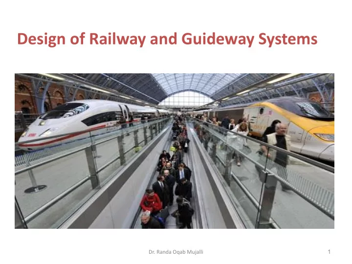
Design of Railway and Guideway Systems
- Dr. Randa Oqab Mujalli
Design of Railway and Guideway Systems 1 Dr. Randa Oqab Mujalli - - PowerPoint PPT Presentation
Design of Railway and Guideway Systems 1 Dr. Randa Oqab Mujalli Service Characteristics of Rail Transportation 1. Service safety 2. Travel speed 3. Performance reliability 4. Comfort and convenience 5. Travel cost 2 Passenger trains A
1
2
3
1. High-speed rail: speeds above 200 km/h 2. Maglev: over 500 km/h 3. Inter-city trains: connecting cities in the fastest time possible, bypassing all intermediate stations a) Regional trains: calling at all intermediate stations between cities, serving all lineside communities b) Higher-speed rail: can operate at top speeds that are higher than conventional inter-city trains but the speeds are not as high as those in the high-speed rail services. 4. Short-distance trains a) Commuter trains: serving the city and its suburbs. 5. Long-distance trains: travel between many cities and/or regions of a country, and sometimes cross several countries. 6. Within cities a) Rapid transit: Large cities often have a metro system, also called underground, subway or tube. Their railroads are separate from other traffic, usually without level crossings. Usually they run in tunnels in the city center and sometimes on elevated structures in the outer parts of the city. They can accelerate and decelerate faster than heavier, long-distance trains. b) Tram c) Light rail: an intermediate form between a tram and a train, similar to a subway except that it may have level crossings. d) Monorail: to meet medium-demand traffic in urban transit
Passenger trains
A passenger train is one which includes passenger-carrying vehicles which can often be very long and
and one or more unpowered trailers known as coaches, cars or carriages.
and operational efficiency of the facility but also influence the disbenefits to or negative impact on nearby communities and the environment.
a basis for the selection of a preliminary and final location.
4
Criteria Influencing Factors Construction costs Functional classification/ design type; topography and soil conditions; current land use User costs Traffic volume; facility design features (e.g., gradients, intersections); operating conditions (e.g., speeds, traffic control systems) Environmental impact Proximity to sensitive areas; design features to mitigate impacts Social impacts Isolation or division of neighborhoods; aesthetics of design; fostering of desired development patterns Acceptance by various interest groups Government agencies; private associations and firms; neighborhood groups and the general public
5
Examples of criteria to be used in facility location decisions
6
7
Circular Curves
100 ft arc (arc definition)
8
𝟑𝝆𝑺 𝟒𝟕𝟏 = 𝟐𝟏𝟏 𝑬 𝐄 = 𝟔𝟖𝟑𝟘. 𝟔𝟗 𝑺
subtended by a 100 ft chord (chord definition)
9
𝒕𝒋𝒐 𝟐 𝟑 𝑬 = 𝟔𝟏 𝑺
Layout of a Simple Horizontal Curve R = Radius of Circular Curve BC = Beginning of Curve (or PC = Point of Curvature) EC = End of Curve (or PT = Point of Tangency) PI = Point of Intersection T = Tangent Length (T = PI – BC = EC - PI) L = Length of Curvature (L = EC – BC) M = Middle Ordinate E = External Distance C = Chord Length Δ = Deflection Angle
Properties of Circular Curves Other Formulas… Tangent: T = R tan(Δ/2) Chord: C = 2R sin(Δ/2) Mid Ordinate: M = R – R cos(Δ/2) External Distance: E = R sec(Δ/2) - R
intersection to the curve on a radial line is
point of the long chord and the midpoint of the curve is: R-M
Δ/360 = L/2.Pi.R
Example Given: Simple Curve, Δ=27º 34’ 40’’, D=2º 30’ Full Station= 100ft
Required: R, T, E, Lc, M, L, St. Of P.C, St. of P.T
Horizontal Alignment Design Criteria for Railways and Gudeways Because rail and guideways can not shift laterally, main line tracks and guideways cannot be designed with sudden changes in horizontal alignment. Horizontal curvature limits the speed of rail vehicles and increase the risk of derailments and overturning accidents. Generally speaking, For main railroad lines: Flat curves 1°- 3° Sharp curves 8°- 10° > 10° seldom used
19
16° or even 24° curves have been utilized in mountainous areas, or on low-speed approaches to terminals in urban areas 40° curves have been used in railroad yards
20
21
Minimum recommended curve radii for urban passenger systems System/ Criteria Source Main Lines, m (ft) Yards and Secondary Tracks, m (ft) Metropolitan Atlanta Rapid Transit Authority (MARTA) 229 (750) 107 (350) Montreal Bureau de Transport Metropolitan 140 (459) 52 (170) Italian Transport Organization (UNIFER) 150 (492) 75 (246)
22
Superelevation of railway and transit guideway curves
23
Track level in place indicating 5" of superelevation on the outside rail of a curve.
direction and the track must resist this movement, and force the train to turn.
forces being at play: – Weight – Resisting forces excreted by the rails – Centrifugal force 𝐺 = 𝑛𝑤2 𝑆 = 𝑋𝑤2 𝑆 m= mass of car, kg (lb) v= velocity, m/sec (ft/sec) R= radius of curve, m (ft) g= acceleration of gravity, 9.08 m/sec2 (32.2 ft/sec2)
24
Radial Force and Design Speed Radial forces act on a vehicle as it travels around a curve and this is why transition curves are necessary A vehicle of mass m, travelling at a constant speed v, along a curve of radius r, is subjected to a radial force P (centripetal) such that: This force acting on the vehicle is trying to push the vehicle back on a straight
Roads are designed according to a ‘design speed’ which is constant for a given stretch of roadway. Thus a vehicle must be able to comfortable and safely travel the length of a given stretch of road at the design speed regardless of bends etc.
26
27
resultant force, T, to be perpendicular to the plane of the top of the rails. By similar triangles, it can be shown that: 𝐹 𝐻 = 𝐺 𝑈 For small angles where sines and tangents are approximately equal, the following relationship is essentially correct: 𝐹 𝐻 = 𝐺 𝑈 = 𝑤2 𝑆 Where, G: is the distance between center to center of rails
28
𝐹 = 1511 𝑤2 1000 3600
2
9.8 𝑆 = 11.9𝑤2 𝑆 𝐹 = 59.5 𝑤2 5280 3600
2
32.2 𝑆 = 3.97𝑤2 𝑆
an elevation about 3 in. higher than that for equilibrium
29
The use of Transition Curves Transition curves can be used to join two straights in one of two ways:
Composite Curves
Wholly Transitional Curves
A wholly transitional curve consists of two transitional curves of equal length with no central arc. The radius of this curve is constantly changing and therefore the force is constantly changing. There is only one point Tc (the common tangent point) at which P is a maximum. This means wholly transitional curves are safer than composite curves. However, they cannot always be fitted between two straight due to minimum radius requirements.
Spirals or Transition Curves for Railways and Transit Guideways Railroad cars or guideways are restrained by their tracks or guideways and cannot shift laterally. For this reason, spiral transition curves are used extensively in mainline railroad design. American Railway Engineering Association (AREA) recommends using spiral curves on all mainline tracks between tangent and curve and between different degrees of curvature where compound curves are used.
32
A transition curve is sometimes used in horizontal alignment design It is used to provide a gradual transition between tangent sections and circular curve sections. Different types of transition curve may be used but the most common is the Euler Spiral.
Properties of Euler Spiral (reference: Surveying: Principles and Applications, Kavanagh and Bird, Prentice Hall]
TS SC CS ST BC’ EC’ Δs Δs Δc
35
Radius of the spiral =radius of tangent(decreases gradually The amount that The circualr curve Is shifted in from the Main tangent
11/12/2014
36
11/12/2014
According to AREA, the recommended formula for the minimum length of the spiral is: In metric system: L= 0.01216EuV L=0.744Ea In traditional U.S. units: L= 1.63EuV L=62Ea L: desired minimum length of spiral, m(ft) Eu: unbalanced elevation, mm (in.) Ea: actual elevation, mm (in.) V: maximum train speed, km/h (mph)
37
length or where the cost of realignment would be prohibitive, the short spiral as defined by:
38
spiral length for light rail vehicles:
39