
SLIDE 1
1
Multiprocessor Allocation and Scheduling using Advanced Optimization Technology
- L. Benini, M. Milano, D. Bertozzi*
- M. Lombardi, A. Guerri, M. Ruggiero
Università di Bologna, *Università di Ferrara
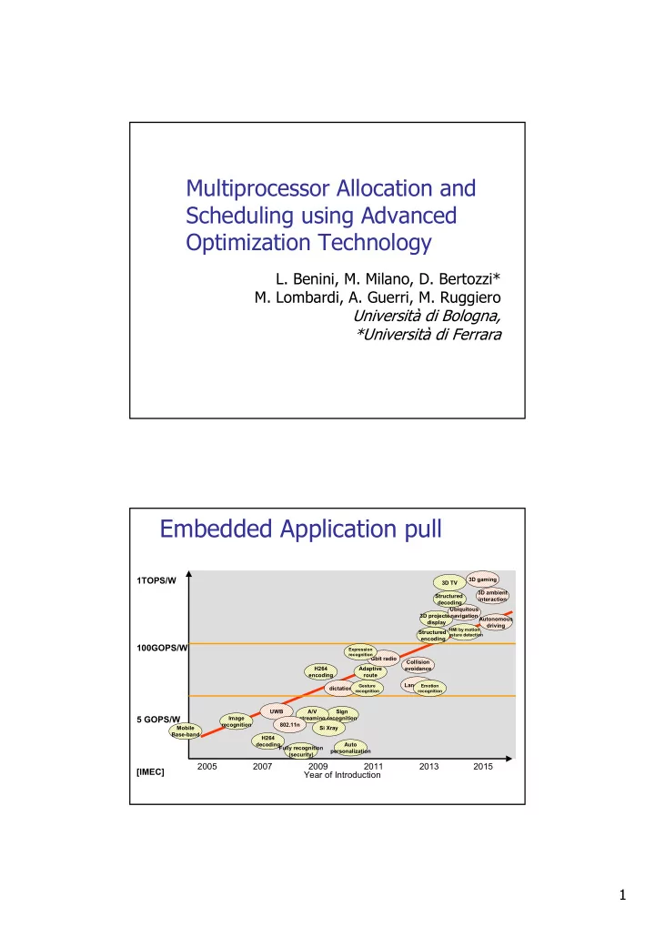
Embedded Application pull
Year of Introduction 2005 2007 2009 2011 2013 2015 5 GOPS/W 100GOPS/W
Sign recognition A/V streaming Adaptive route Collision avoidance Autonomous driving 3D projected display
HMI by motion Gesture detection
Ubiquitous navigation Si Xray Gbit radio UWB 802.11n Structured encoding Structured decoding 3D TV 3D gaming H264 encoding H264 decoding Image recognition Fully recognition (security) Auto personalization dictation 3D ambient interaction Language
Emotion recognition Gesture recognition Expression recognition
Mobile Base-band
1TOPS/W [IMEC]