
SLIDE 1
Inf2C Computer Systems - 2013-2014 1
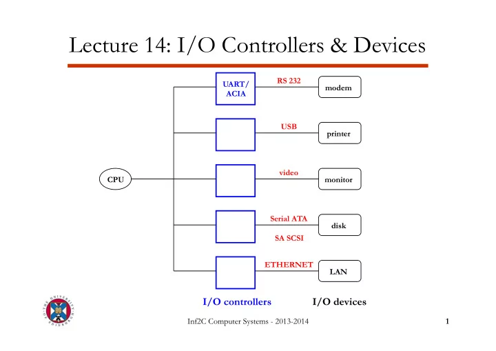
Lecture 14: I/O Controllers & Devices
I/O controllers
CPU UART/ ACIA modem printer monitor disk RS 232 USB video Serial ATA SA SCSI
I/O devices
LAN ETHERNET
Examples of I/O Devices Device Behaviour Partner Data Rate - - PowerPoint PPT Presentation
Lecture 14: I/O Controllers & Devices RS 232 UART/ modem ACIA USB printer video CPU monitor Serial ATA disk SA SCSI ETHERNET LAN I/O controllers I/O devices Inf2C Computer Systems - 2013-2014 1 Examples of I/O Devices Device
Inf2C Computer Systems - 2013-2014 1
I/O controllers
CPU UART/ ACIA modem printer monitor disk RS 232 USB video Serial ATA SA SCSI
I/O devices
LAN ETHERNET
Inf2C Computer Systems - 2013-2014 2
Device Behaviour Partner Data Rate (Mbit/sec) Keyboard Input Human 0.001 Mouse Input Human 0.004 Voice input Input Human 0.26 Laser printer Output Human 3.2 Graphics display Output Human 800-8000 Network/LAN Input or output Machine 100-10000 Magnetic disk Storage Machine 800-3000
Inf2C Computer Systems - 2013-2014 3
Tx data wire (CPU to I/O device) Rx data wire (I/O device to CPU) GROUND wire
Inf2C Computer Systems - 2013-2014 4
1 idle (1) start bit (0) data (7 or 8 bits) parity bit stop bit (1)
Inf2C Computer Systems - 2013-2014 5
shift register shift register serial data in receiver status Rx data register Tx data register transmitter status serial data out write control data data read control RECEIVER TRANSMITTER FROM/TO I/O device FROM/TO processor
1 8 8 1 1 1 8 8
Inf2C Computer Systems - 2013-2014 6
Inf2C Computer Systems - 2013-2014 7
Inf2C Computer Systems - 2013-2014 8
Memory bus
CPU
Cache Main memory Bus adapter I/O bus I/O controller I/O controller I/O controller
Inf2C Computer Systems - 2013-2014 9
Tx data register Rx data register status register WRITE
8
READ
8
READ
8
UART data 128 bits address 32 bits memory bus from processor
receiver status bit receiver status bit
data 8 bits address 8 bits read/ write control 2 bits I/O bus from
Inf2C Computer Systems - 2013-2014 10
Inf2C Computer Systems - 2013-2014 11
arm + head platter axis track sector arm + head
Inf2C Computer Systems - 2013-2014 12
Dependent on spinning speed
Inf2C Computer Systems - 2013-2014 13
High-level commands
Inf2C Computer Systems - 2013-2014 14
Inf2C Computer Systems - 2013-2014 15
Inf2C Computer Systems - 2013-2014 16
Inf2C Computer Systems - 2013-2014 17
address
Address register
data
DMA Controller disk Data register Length register CPU Memory
control Bus Request Bus Grant
FROM/ TO
Inf2C Computer Systems - 2013-2014 18
Inf2C Computer Systems - 2013-2014 19