FINITE ELEMENT MODELLING OF CFRP PLATES UNDER CRUSHING H.A.Israr 1 , - - PDF document

finite element modelling of cfrp plates under crushing
SMART_READER_LITE
LIVE PREVIEW

FINITE ELEMENT MODELLING OF CFRP PLATES UNDER CRUSHING H.A.Israr 1 , - - PDF document

18 TH INTERNATIONAL CONFERENCE ONCOMPOSITEMATERIALS FINITE ELEMENT MODELLING OF CFRP PLATES UNDER CRUSHING H.A.Israr 1 , S. Rivallant 1* , H. Zeng 1 , JJ. Barrau 1 1 Universit de Toulouse; INSA, UPS, Mines Albi, ISAE; ICA (Institut Clment


slide-1
SLIDE 1

18THINTERNATIONAL CONFERENCE ONCOMPOSITEMATERIALS

1 Introduction New development of aircraft and helicopter structural designs has included more aspect of composite materials thanks to their technical advantages especially as crash-absorbing element. Previous studies [1-3] have proved that with careful design, composite structure can become an excellent energy absorbing component. Due to this reason many studies [4-6] of composite crashworthiness have been done in the recent years. However, from a numerical point of view, there is still a lake of studies in numerical simulation. Most of the models developed in the last few years [7] are based on global tests characterisations that make the model strongly dependant on global parameters, which do not permit to have predictive

  • models. Some models [8] are based on material

characteristics, but often need an a priori knowledge

  • f the crush damage mode developed in the crush

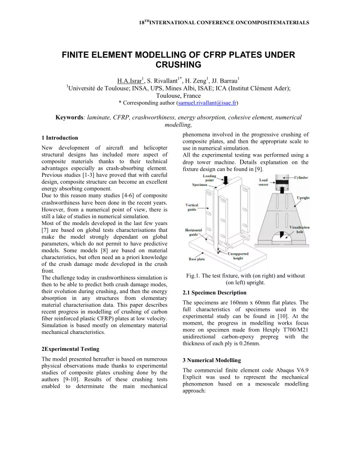
front. The challenge today in crashworthiness simulation is then to be able to predict both crush damage modes, their evolution during crushing, and then the energy absorption in any structures from elementary material characterisation data. This paper describes recent progress in modelling of crushing of carbon fiber reinforced plastic CFRP) plates at low velocity. Simulation is based mostly on elementary material mechanical characteristics. 2Experimental Testing The model presented hereafter is based on numerous physical observations made thanks to experimental studies of composite plates crushing done by the authors [9-10]. Results of these crushing tests enabled to determinate the main mechanical phenomena involved in the progressive crushing of composite plates, and then the appropriate scale to use in numerical simulation. All the experimental testing was performed using a drop tower machine. Details explanation on the fixture design can be found in [9]. Fig.1. The test fixture, with (on right) and without (on left) upright. 2.1 Specimen Description The specimens are 160mm x 60mm flat plates. The full characteristics of specimens used in the experimental study can be found in [10]. At the moment, the progress in modelling works focus more on specimen made from Hexply T700/M21 unidirectional carbon-epoxy prepreg with the thickness of each ply is 0.26mm. 3 Numerical Modelling The commercial finite element code Abaqus V6.9 Explicit was used to represent the mechanical phenomenon based on a mesoscale modelling approach:

FINITE ELEMENT MODELLING OF CFRP PLATES UNDER CRUSHING

H.A.Israr1, S. Rivallant1*, H. Zeng1, JJ. Barrau1

1Université de Toulouse; INSA, UPS, Mines Albi, ISAE; ICA (Institut Clément Ader);

Toulouse, France

* Corresponding author (samuel.rivallant@isae.fr)

Keywords: laminate, CFRP, crashworthiness, energy absorption, cohesive element, numerical modelling,

slide-2
SLIDE 2

Th m fr st qu (f sp th H le m fo el as re m w Fo ca m sim D A

  • meshin
  • cohesiv

accoun fractur

  • cohesiv

rupture mass a

  • modell

rupture fragme fragme extrem

  • contact

debris his model i mixed-mode agmentation) acking seque uasi-isotropic fig.3). The nu playing mode he experiment However, the ead to problem mode simulatio

  • cus more on

lements and t s an improvem epresent bette

  • mode. The sim

with a falling

  • rce/displacem

ameras of the make precise mulation. Fig.2. Mod Fragme Debris Accumulatio x y z ng of each ply ve elements b nt delaminat re mechanics ve elements e of plies into and volume ling of fra e criteria in ents) and sp ents localised mity t laws to rule wedge appea s applied to phenomen ) (fig.2) of ence [(0°/90°) c laminate i umerical mod e have been d tal works and 2D continuu ms of instabil

  • n. Thus, the

n mixed-mod triggering me ment of the pr er crush initi mulation is b mass at the ment curve e experimenta correlation b elling: fragm entation

  • n

y of the comp between plies ion and spl criteria inside plies

  • fragment wi

agmentation n the ply (f ecific criteri d at the cru e debris accum aring.

  • simulate th

non (splay f laminated )*4]sym and a in pure spla del for the c done and com d gives good um shell ele lity in the cas current mod de model usin echanism of 4 revious mode iation and fr based on a d e initial spee and the al works are between expe entation and s posite, s to take into laying with to represent ithout losing thanks to for big size a for small ushing front mulation and he crushing ying and plate with a (0/45/90)n aying mode case of pure mpared with results [11]. ements used se of mixed- elling works ng 3D solid 45° chamfer el in order to ragmentation dynamic test d of 9 m/s. high speed available to eriment and splaying. Splaying Fig 3.1 Mo The lam Only 1 reduce have re plate a reason represe experim are uni solid el The dim thickne directio (COH3 model also ha mention bottom promot [12]. D in the f during nodes a betwee the gui coeffici Coh inte g.3. Modellin

  • del Descript

minated plate 100 mm leng the calculatio ealistic bound and the guid

  • nly one elem

ent the 60mm ments show th

  • iform. The p

lement C3D8 mension of e ess and also

  • ns. The 8

3D8) with ze the interface as been place ned earlier (fi

  • f the plate d

te an initial fa Details of lam fig.5. In orde the test, an a at the top of n the plate e ides is ruled ient μ=0.1. Fig.4. Cohes hesive elemen rface bonding ng: pure splay tion e is modelled gth of the pl

  • n time, whic

dary conditio

  • des. Besides

ment of 0.25m m width of hat deformati plate lay-up i 8 (8 nodes wi each element

  • 0.25mm

nodes 3D ro thickness e bonding be d inside the fig.4). Nodes a do not have a ailure as used inated plate m er to represen additional ma f the plate. Th elements, the by general c sive element a nts: g Cohesi insid ying mode [11 in three-dime late is mode ch is long eno

  • ns on the m

that, for the mm width is u the plate b ions along the is modelled ith full integr t is 0.25mm in the othe cohesive el have been u etween the p plies for the and interface any imperfect d in the recen model are pre nt the falling ass is added he contact be e metallic pla contact with f arrangement. ive elements: de the plies 1]. ension. elled to

  • ugh to

metallic e same used to because e width by 3D ration). in the er two ements used to

  • plies. It

reason s at the tions to nt study esented weight

  • n the

ehavior ate and friction

slide-3
SLIDE 3

3. Th an da w W th m di D (f th ch Fig .2 Delaminat he delaminati nd consist of amage evolut with the follow Where (tn, ts a he two local matrix, (δn, δs irection. Fig amage initia fig.6) reaches he rupture haracterisation

− = ⎪ ⎭ ⎪ ⎬ ⎫ ⎪ ⎩ ⎪ ⎨ ⎧

t s n

T D t t t 1

Rigid Elem Gu x z y g.5. Laminate tion Law ion law is bas f three states tion and a co wing behaviou and tt) are str shear direct s and δt) are g.6. Evolution ates when on its maximal value c n test of comp

⎢ ⎢ ⎢ ⎣ ⎡ ×

nn

K K D

ment : uides e plate model. sed on tractio s: a damage mpletely sep ur law: resses in the tions, [K] is e the separati n of damage. ne of the th

  • value. Maxim

calculated posite ply.

⎢ ⎢ ⎢ ⎣ ⎡ × ⎥ ⎥ ⎥ ⎦ ⎤

tt ss

K K δ δ δ

V0=9 m/s Rigid Metal Laminate . n-separation initiation, a aration state (1) normal and the rigidity ions in each hree stresses mal value is from the

⎥ ⎥ ⎥ ⎦ ⎤

t s n

δ δ δ

Element : llic Plate The da softenin so, the release betwee The sa elemen energy to repre The co from t represe in expe Table 4 Resu Both th curve a being Genera good c simulat The ill both e present The de experim

  • ccurre

same d It show capturin consist the sam

Solid elemen Interfac Inter- lamina Interfac Inside plies

amage propa ng law. The l e energy abs rate at inte n three mode ame law have nts inside the and nominal esent the ruptu

  • hesive elem

the baseline ent the right c eriments.

  • 1. Mechanica

lt Discussion he numericall and the crush compared w ally, results o

  • rrelation bet

tion. lustrations of experimental ted in fig.7 at formation seq ment was very ed at the sam elamination l ws this sim ng the initia both splayin me time.

d nt E1 (GPa) 125 ce:

  • ar

Yt (MPa) 350 ce: e s Yt (MPa) 1750

agation is ru linear decrea sorbed is eq erface in eac s is chosen lin

ic i

G G e been applie plies but wi traction stres ure of the plie ments propert e values to crushing morp al characterist simulation. ns ly simulation hing physical with the ex

  • f numerical

tween behavi f crash initia and num different inte quence of sim y similar to e me displaceme

  • cation of the

mulation mod ation of the ng and fragm

E2 (GPa) 9 Sc (MPa) (m 150 Sc (MPa) (m 150

uled by a b se is calculat qual to the ch mode. Co near: ed on the co ith higher va ss in order to b es. ties were inc

  • more acc

phology as ob tic of T700/M n force/displac l phenomeno xperimental r modelling s iour during te ation obtained merical mode ervals of time mulation mod each other (in ent followed e related plies del is capa crushing pla mentation mo

G12 (GPa) 5 GI mJ/mm2) (m 2 GI mJ/mm2) (m 120

bilinear ted and energy

  • upling

(2)

  • hesive

lues of be able creased curately btained M21 for cement n have results. show a est and d from el are s. del and itiation by the s). ble of ate that

  • des at

υ12

0.33 GII mJ/mm2) 1.2 GII mJ/mm2) 1.2

slide-4
SLIDE 4

Fig.7.Comparison between experiment and simulation: visualization of mixed-mode failure during crash initiation. However, during the progressive crushing, the simulation model failed to have a stable failure mode of fragmentation as recorded in experiment

  • works. It seems like the fragmentation mode only

arises during the initiation till just before the specimen transitioned into a progressive crushing

  • mode. After that, it has a tendency to transform into

splaying failure mode. Fig.8. Visualization of mixed mode failure just before the progressive crushing. For the analysis

  • f

energy dissipation, force/displacement curves of numerical model and experiment were compared as in the fig.9. Fig.9. Force/displacement curve. The maximum forces for both curves are close to each other and occurred almost at the same

  • displacement. Both results also show after exceeding

4.5-5mm of plate displacement, the force did not

increase but flattened out as the specimen transitioned into a progressive crushing mode. The big difference in the crushing plateau during the progressive crushing between these two curves was due to the absence of the stable fragmentation mode in the simulation model as discussed earlier. 5 Conclusions The aim of this study is to propose a simulation model for mixed-mode in plates subjected to crush load, only dependent on the elementary material characteristics of the laminate. However, up to this moment this simulation gives good correlation on the crash initiation. It needs to be improved in order to have a stable fragmentation mode which is more efficient in terms of energy absorption. t=0.18ms t=0.5ms t=0.43ms t=0.63ms

slide-5
SLIDE 5

Acknowledgment: Numerical simulations have been performed with the computing resources of CALcul en MIdi Pyrénées (CALMIP, Toulouse, France). References

[1] D.Hull “A unified approach to progressive crushing

  • f

fibre reinforced tubes”. Compos Science Technology1991;40:377–421. [2] S.Ramakrishna “Microstructural design of composite materials for crashworthy structural applications”. Materials & Design, Vol. 18, No. 3, pp. 167]173, 1997. [3] G. Barnes, I. Coles, R. Roberts, D.O Adam, D.M Garner “Crash safety assurance strategies for future plastic and composite intensive vehicles (PCIVs)”. Final report Volpe National Transportation Systems Center Cambridge, MA 02142. [4] P. Feraboli, M. Rassaian “Standardization of analytical and experimental methods for crashworthiness energy absorption of composite materials”. Presented at the Federal Aviation Administration Joint Advanced Materials & Structures (JAMS) 5th Annual Technical Review Meeting, Wichita, KS July 21-22, 2009. [5] A.G. Mamalis, M. Robinson, D.E. Manolakos, G.A. Demosthenous, M.B. Ioannidis, J. Carruthers “Crashworthy capability of composite material structures”. Composite structures 1997; 37:109-134.9. [6] M.W. Joosten, S. Dutton, D. Kelly, R. Thomson “Experimental and numerical investigation of the crushing response of an open section composite energy absorbing element”. Composite Structures 93 (2011) 682–689. [7] C. McGregor, R. Reza Vaziri, X. Xiao “Finite element modelling of the progressive crushing of braided composite tubes under axial impact”. International Journal

  • f

Impact Engineering, Volume 37, Issue 6, June 2010, Pages 662-672. [8] S.T. Pinho, P.P. Camanho, M.F. de Moura “Numerical simulation of the crushing process of composite materials”, Int J Crash 2004;9(3):263-276. [9] D. Guillon, S. Rivallant, JJ. Barrau, C. Petiot, P. Thevenet, N. Pechnick “Initiation and propagation mechanisms of progressive crushing in carbon-epoxy laminated plates”. ECCM-13, Stockholm, Sweden, June 2008. [10] A.V. Duong, S. Rivallant, JJ. Barrau, C. Petiot, B. Malherbe “Influence of speed on the crushing behavior of composite plates”. ACCM-7, Taipei, Taiwan, Nov. 2010. [11] D. Guillon, S. Rivallant, JJ. Barrau, C.Petiot, P. Thevenet, B. Malherbe “Experimental and numerical study of the splaying mode crush of CFRP laminates”. ICCM-17, Edinburgh, UK, July 2009. [12] S. Palanivelu, M.V. Paepegem, J. Degrieck, D. Kakogiannis, J.V Ackeren, D.V Hemelrijck, J. Wastiels, J. Vantomme “Parametric study of crushing parameters and failure patterns

  • f

pultruded composite tubes using cohesive elements and seam: Part II – Multiple delaminations and initial geometric imperfections”. Polymer Testing 29 (2010) 803–814.