
SLIDE 1
1 Material Properties
Illumination Models / BRDFs
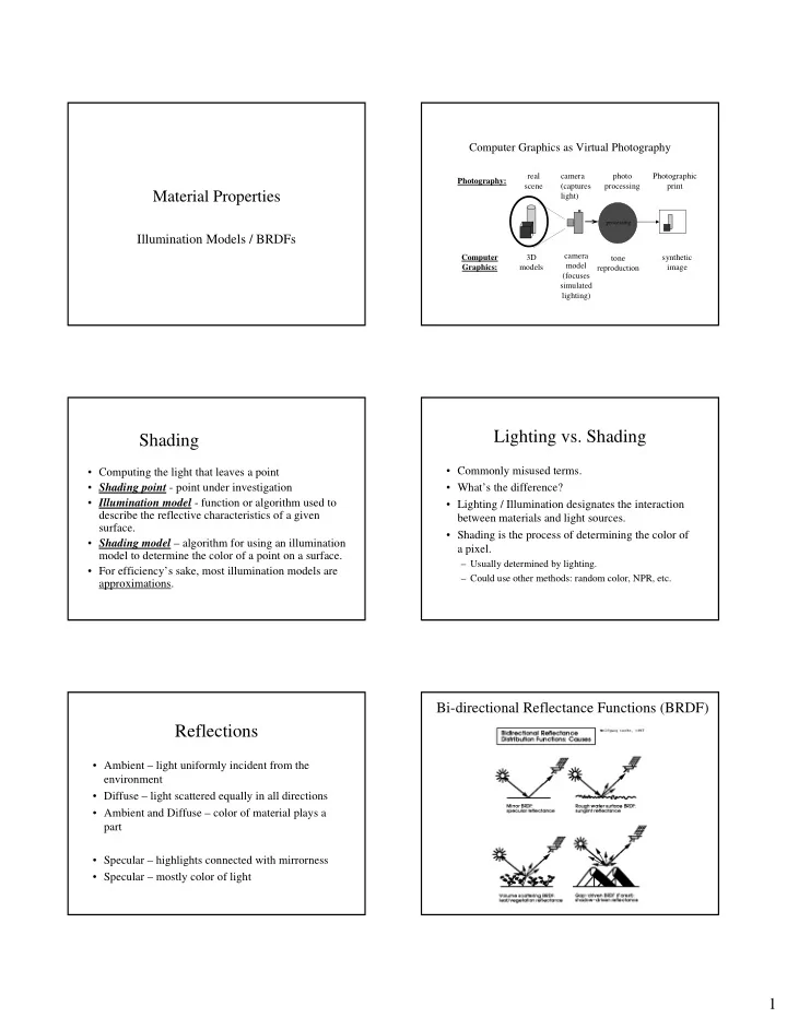
Computer Graphics as Virtual Photography
camera (captures light) synthetic image camera model (focuses simulated lighting)
processing
photo processing tone reproduction real scene 3D models Photography: Computer Graphics: Photographic print
Shading
- Computing the light that leaves a point
- Shading point - point under investigation
- Illumination model - function or algorithm used to
describe the reflective characteristics of a given surface.
- Shading model – algorithm for using an illumination
model to determine the color of a point on a surface.
- For efficiency’s sake, most illumination models are
approximations.
Lighting vs. Shading
- Commonly misused terms.
- What’s the difference?
- Lighting / Illumination designates the interaction
between materials and light sources.
- Shading is the process of determining the color of
a pixel.
– Usually determined by lighting. – Could use other methods: random color, NPR, etc.
Reflections
- Ambient – light uniformly incident from the
environment
- Diffuse – light scattered equally in all directions
- Ambient and Diffuse – color of material plays a
part
- Specular – highlights connected with mirrorness
- Specular – mostly color of light