Mismatch, damping and emittance growth o r LHC beam emittance - - PowerPoint PPT Presentation

▶
mismatch damping and emittance growth
SMART_READER_LITE
LIVE PREVIEW

Mismatch, damping and emittance growth o r LHC beam emittance - - PowerPoint PPT Presentation

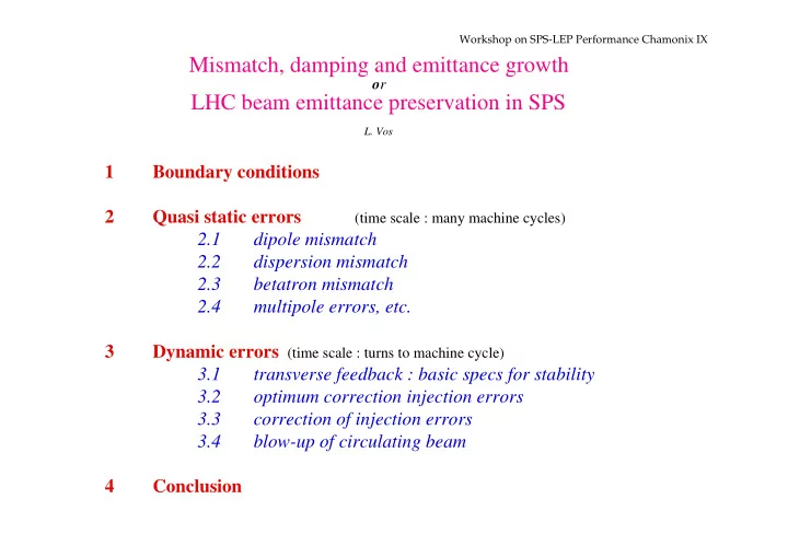
Workshop on SPS-LEP Performance Chamonix IX Mismatch, damping and emittance growth o r LHC beam emittance preservation in SPS L. Vos 1 Boundary conditions 2 Quasi static errors (time scale : many machine cycles) 2.1 dipole mismatch 2.2


slide-1
SLIDE 1

Workshop on SPS-LEP Performance Chamonix IX

Mismatch, damping and emittance growth

  • r

LHC beam emittance preservation in SPS

  • L. Vos

1 Boundary conditions 2 Quasi static errors

(time scale : many machine cycles)

2.1 dipole mismatch 2.2 dispersion mismatch 2.3 betatron mismatch 2.4 multipole errors, etc. 3 Dynamic errors (time scale : turns to machine cycle) 3.1 transverse feedback : basic specs for stability 3.2

  • ptimum correction injection errors

3.3 correction of injection errors 3.4 blow-up of circulating beam 4 Conclusion

slide-2
SLIDE 2

Workshop on SPS-LEP Performance Chamonix IX

  • 2-

1 Boundary conditions input emittance : 3.0 µmrad

  • utput emittance

: 3.5 µmrad

Total blow-up budget attributed to SPS : 0.5 µmrad

many contenders to have a piece of the cake

slide-3
SLIDE 3

Workshop on SPS-LEP Performance Chamonix IX

  • 3-

2 Quasi static errors 2.1 dipole mismatch

  • r dipole injection error

Transverse feedback (see later) can only handle errors below some limit

■

measure and correct static steering required when limit exceeded (injection error watch dog)

these errors do not contribute to emittance blow-up if treated correctly

slide-4
SLIDE 4

Workshop on SPS-LEP Performance Chamonix IX

  • 4-

2.2 dispersion mismatch Off momentum particles of a well injected beam (dipole) will be subjected to oscillations, filamentation and beam blow up. ∆ ∆ ε βγ β δ =       2

2 y

D p p

0.1 0.2 0.3 0.4 0.5 0.02 0.04 0.06 0.08

error in D / m emittance increase /µmrad for δp/p = 10

  • 3

■measure and correct measure trajectory of beam with small momentum spread (pencil beam, long bunches)

slide-5
SLIDE 5

Workshop on SPS-LEP Performance Chamonix IX

  • 5-

2.3 betatron mismatch

1

λ

ε λ λ ε = +

( )

−

1 2

2 2

Emittance increase due to quadrupole errors is multiplicative

slide-6
SLIDE 6

Workshop on SPS-LEP Performance Chamonix IX

  • 6-

1 1.05 1.1 1.15 1.2 1.25 1.3 1.35 1.4 3 3.1 3.2 3.3 3.4 3.5 3.6 3.7

µmrad mismatch factor λ

slide-7
SLIDE 7

Workshop on SPS-LEP Performance Chamonix IX

  • 7-

PS, transfer line PS-SPS, SPS

  • ptics well known and stable

ejection/ injection SPS injection trajectory clear of machine magnet gaps PS ejection trajectory more difficult to model (off-centered beams, stray-fields) some uncertainty on the exact optics persists

■measure and correct ■ install multiturn interceptive high resolution profile monitor in SPS ■ develop and install non interceptive quadrupole BPM (watch dog function)

slide-8
SLIDE 8

Workshop on SPS-LEP Performance Chamonix IX

  • 8-

2.4 multipole errors, etc.

■Avoid

non-linear resonances HF single bunch instabilities

■measure and correct =====> need a precise tune control and good betatron coupling compensation (much easier for LHC beam than for pbar-p beam : only zero order since no tune split as for low β

  • ptics !)
slide-9
SLIDE 9

Workshop on SPS-LEP Performance Chamonix IX

  • 9-

3 Dynamic errors Only dipole errors considered 3.1 transverse feedback : basic specs for stability Stability against RW imposes a minimum gain that rolls off from a min frequency to fb/2 ( 20 MHz).

G R Q E e Z i =

⊥

max G for ultimate intensity : 0.08

  • ccurs at ~ 3 frev due to non-uniform filling
slide-10
SLIDE 10

Workshop on SPS-LEP Performance Chamonix IX

  • 10-

3.2

  • ptimum correction injection error

In principle observation and correction can be done at any harmonic of fb. OK for observation but not for correction :

ideal correction correction at <f> correction at <f>/2 correction amplitude time

Comparison between base-band and high frequency corrections deflector frequency below <f>/2 = 80 MHz choice of base band is good!

slide-11
SLIDE 11

Workshop on SPS-LEP Performance Chamonix IX

  • 11-

3.3 correction of injection errors 3.3.1 errors

  • fast kickers

normalised deflection CERN kickers ∆x

m γ β = 0 1 .

====> total for kickers : eK = 0 5

. σ

fast kickers upstream SPS rise time < 100 ns ⇒ power bandwidth of 5 MHz.

  • bending magnets and septa ripple in transfer line

bendings in injection line

eB = 0 5 . σ

septa in injection line

eS = 0 25 . σ

e e e e

inj K B S 2 2 2 2 2

0 375 1 2 = + +

( ) =

⇒ γ β γσ β ε .

[ assumed similar H and V !] einj = 2.3 mm

slide-12
SLIDE 12

Workshop on SPS-LEP Performance Chamonix IX

  • 12-

3.3.2 correction by feedback

∆ ∆ ε τ τ = +       = +       1 2 1 1 1 2 1 1 2 5

2 2 2 2

e e G Q

inj dc d inj sc

.

direct space charge

∆Q i R Q Z R E e R Q

sc sc

= −

( )

=       ε σ π γ ε γ σ 2 2

2 2 2

ˆ

(ultimate intensity)

0.05 0.1 0.15 0.2 0.2 0.4 0.6 0.8

Gain emittance increase /µmrad

slide-13
SLIDE 13

Workshop on SPS-LEP Performance Chamonix IX

  • 13-

θ ε β γ = Gtotal

kic

2

ker ⇒

E dl

⊥

∫

allowed blow-up µmrad 0.3 einj

2

µmrad 1.5 gain (RW) 0.08 gain (injection) 0.1 total gain 0.18 deflection ( β= 45m) µrad 6.3 E dl

⊥

∫

kV 165 power band-width MHz 5 Gain and deflection requirements for SPS

slide-14
SLIDE 14

Workshop on SPS-LEP Performance Chamonix IX

  • 14-

Note Commissioning beam

  • 10x less intensity
  • √10 less emittance
  • same errors
  • fortunately √10 less ∆Qsc

∆ε ~ 0.06 µmrad for same G

slide-15
SLIDE 15

Workshop on SPS-LEP Performance Chamonix IX

  • 15-

3.4 blow-up of circulating beam

d dt x T Q ε γ β =

2

∆

x is the r.m.s. noise level

noise level µV 40 effective monitor Z Ω/m 40 resolution A•µm 1 average coast time sec 7.2 max blow-up µmrad 0.1 max rate µmrad/s 0.014 max x for max rate µm 4 dynamic(digital) 5300 analog x for ultimate (1.09 A) µm 0.9 analog x for nominal (0.64 A) µm 1.5 Resolution and emittance blow-up in SPS

slide-16
SLIDE 16

Workshop on SPS-LEP Performance Chamonix IX

  • 16-

4 Conclusion input emittance : 3.0 µmrad

  • utput emittance

: 3.5 µmrad

Total blow-up budget attributed to SPS : 0.5 µmrad Tight but it can be done

Final quality control with high precision wire scanner beyond and above any suspicion