
SLIDE 1
18TH INTERNATIONAL CONFERENCE ON COMPOSITE MATERIALS
1 Introduction Application of CFRP to cryogenic propellant tanks can significantly reduce the structural weights of space transportation system. However, cracks often develop in CFRP laminates at cryogenic temperature. These cracks cause a leakage of propellant. In order to prevent the propellant leakage, usually liners are attached to CFRP. Research and development of CFRP cryogenic propellant tank with Al alloy liner was carried out [1]. However, debonding between the CFRP wall and inner Al alloy liner occurred in structural test. Usually, there is large thermal expan- sion gap between CFRP and liner materials. The temperature difference between curing temperature and environment temperature caused the thermal residual stress and strain, and the debonding oc- curred on the adhesive. Therefore it is important to investigate fracture toughness of adhesive bonded joint of CFRP laminates and liner for designing CFRP cryogenic tank with the liner. In this study, mode I fracture toughness were measured using DCB tests with three types of bonded specimens. The tests were performed at various temperatures, room temperature,-50˚C and cryogenic temperature (-196˚C). We must consider effects of residual ther- mal stress on energy release rate because there is large difference of coefficient of thermal expansion between CFRP and liner material. However, effect
- f residual thermal stresses is not considered in the
standardized test method, such as ASTM. Recently, Yokozeki [3] formulated corrected equations for evaluating energy release rate with residual stresses. In this study, energy release rates with residual stresses were evaluated using Yokozeki’s correction method. 2 DCB test In this study, three types of bonded specimens were tested: CFRP/Adhesive/CFRP(C/C specimen), Alu- minum/Adhesive/Aluminum (A/A specimen) and CFRP/Adhesive/Aluminum (C/A specimen). Sche- matic
- f
specimen is shown in Fig.1. MR50R/#1063EX prepreg (MITSUBISHI RAYON CO., LTD.) was employed for CFRP. Stacking con- figuration was [0]16. MR50R is a PAN based, mid- dle-modulus, high-strength carbon fiber. #1063EX is a toughened epoxy resin. For Aluminum alloy, A6061-T6 was employed. AF163-2K epoxy film adhesive (3M) bonded CFRP layer and Aluminum
- layer. Grass fiber mesh was used to achieve the uni-
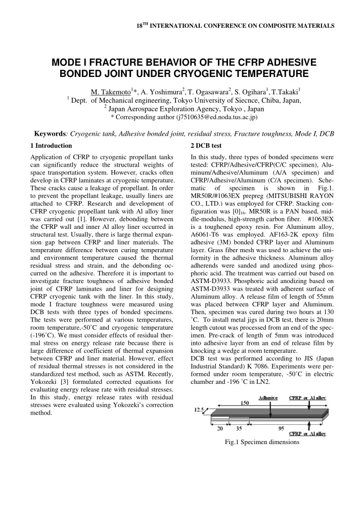
formity in the adhesive thickness. Aluminum alloy adherends were sanded and anodized using phos- phoric acid. The treatment was carried out based on ASTM-D3933. Phosphoric acid anodizing based on ASTM-D3933 was treated with adherent surface of Aluminum alloy. A release film of length of 55mm was placed between CFRP layer and Aluminum. Then, specimen was cured during two hours at 130 ˚C. To install metal jigs in DCB test, there is 20mm length cutout was processed from an end of the spec-
- imen. Pre-crack of length of 5mm was introduced
into adhesive layer from an end of release film by knocking a wedge at room temperature. DCB test was performed according to JIS (Japan Industrial Standard) K 7086. Experiments were per- formed under room temperature, -50˚C in electric chamber and -196 ˚C in LN2. Fig.1 Specimen dimensions
MODE I FRACTURE BEHAVIOR OF THE CFRP ADHESIVE BONDED JOINT UNDER CRYOGENIC TEMPERATURE
- M. Takemoto1*, A. Yoshimura2, T. Ogasawara2, S. Ogihara1, T.Takaki1
1 Dept. of Mechanical engineering, Tokyo University of Siecnce, Chiba, Japan, 2 Japan Aerospace Exploration Agency, Tokyo , Japan