
SLIDE 1
1
9/27/06 CS/ECE 438 - UIUC, Fall 2006 1
Packet Forwarding
9/27/06 CS/ECE 438 - UIUC, Fall 2006 2
Now Arriving at Layer 3
… although layer 2 switches and layer
3 routers are similar in many ways
… and ATM/Virtual Circuits are used
at layer 2 these days
9/27/06 CS/ECE 438 - UIUC, Fall 2006 3
Network Layers and Routers
Application Presentation Physical Transport Session Data Link Network Physical Data Link Network Application Presentation Physical Transport Session Data Link Network Host Router
9/27/06 CS/ECE 438 - UIUC, Fall 2006 4
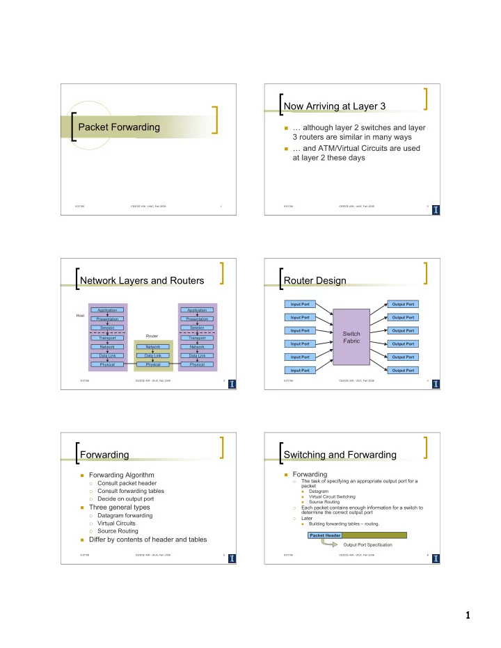
Router Design
Input Port Input Port Input Port Input Port Input Port Input Port Output Port Output Port Output Port Output Port Output Port Output Port
Switch Fabric
9/27/06 CS/ECE 438 - UIUC, Fall 2006 5
Forwarding
Forwarding Algorithm
Consult packet header
Consult forwarding tables
Decide on output port
Three general types
Datagram forwarding
Virtual Circuits
Source Routing
Differ by contents of header and tables
9/27/06 CS/ECE 438 - UIUC, Fall 2006 6
Switching and Forwarding
Forwarding
The task of specifying an appropriate output port for a packet
Datagram
Virtual Circuit Switching
Source Routing
Each packet contains enough information for a switch to determine the correct output port
Later
Building forwarding tables – routing. Packet Header Output Port Specification