
SLIDE 1
Applied Network Research Group Department of Computer Engineering, Kasetsart University 1/28
Digital Carrier Systems
Surasak Sanguanpong nguan@ku.ac.th http://www.cpe.ku.ac.th/~nguan
Last updated: 8 Feb 2001 Applied Network Research Group Department of Computer Engineering, Kasetsart University 2/28
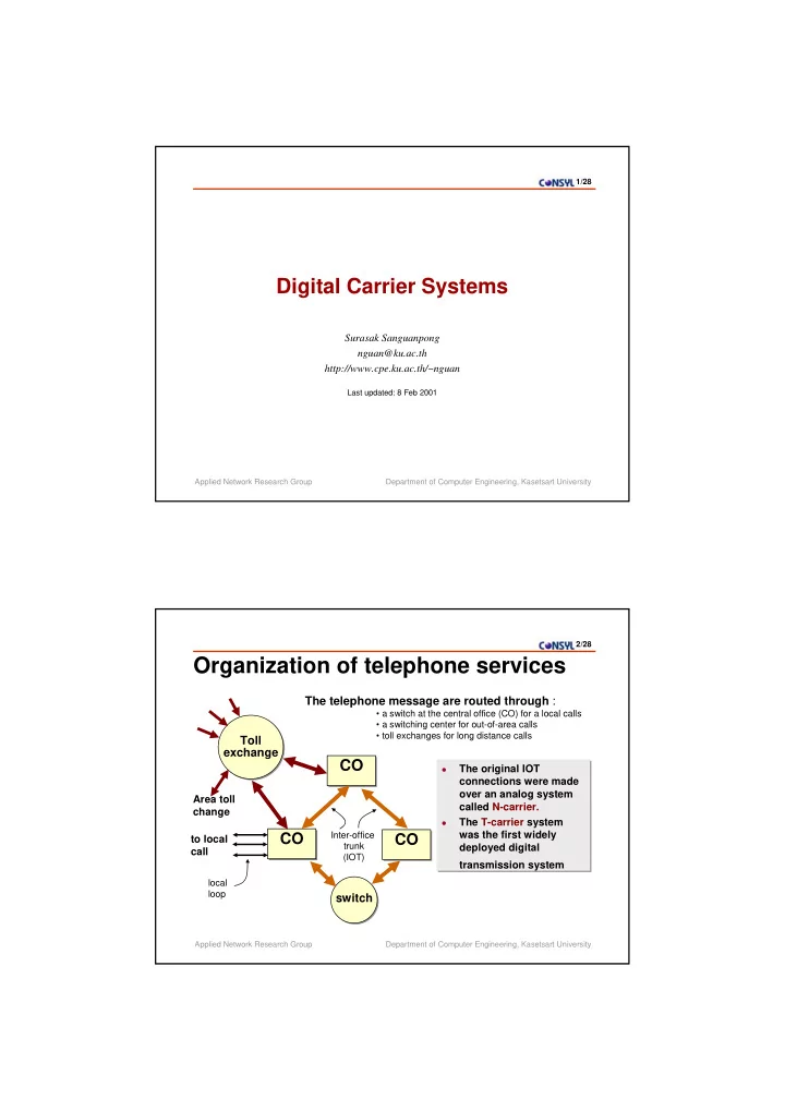
Organization of telephone services
The telephone message are routed through :
- a switch at the central office (CO) for a local calls
- a switching center for out-of-area calls
- toll exchanges for long distance calls
CO CO CO CO CO CO
switch switch
to local call
local loop
Toll exchange Toll exchange
Area toll change
Inter-office trunk (IOT)
- The original IOT
connections were made
- ver an analog system
called N-carrier.
- The T-carrier system
was the first widely deployed digital transmission system
- The original IOT
connections were made
- ver an analog system
called N-carrier.
- The T-carrier system
was the first widely deployed digital transmission system