Phase-field Modeling of Hydride Reorientation in Zirconium Cladding - - PDF document

phase field modeling of hydride reorientation in
SMART_READER_LITE
LIVE PREVIEW

Phase-field Modeling of Hydride Reorientation in Zirconium Cladding - - PDF document

Transactions of the Korean Nuclear Society Virtual Spring Meeting July 9-10, 2020 Phase-field Modeling of Hydride Reorientation in Zirconium Cladding Materials under Applied Stress Wooseob Shin a ,Kunok Chang a a Department of Nuclear


slide-1
SLIDE 1

Phase-field Modeling of Hydride Reorientation in Zirconium Cladding Materials under Applied Stress

Wooseob Shin a ,Kunok Chang a

aDepartment of Nuclear Engineering, Kyung Hee University, Yong-in city, Korea *Corresponding author: kunok.chang@khu.ac.kr

  • 1. Introduction

Dry storage of spent fuel of light-water reactors is already being implemented or strongly considered as a potential option for long-term storage [1]. While it is extremely important to maintain the integrity of the cladding during dry storage, hydride tends to be re- precipitated during dry storage due to hydrogen dissolved in the αmatrix; this has a significant effect on the cladding integrity[2, 3]. Because the adverse effect of circumferential hydrides on the cladding mechanical integrity is less than that of radial hydrides, producers control the texture of the cladding to cause supersaturated hydrogen to be precipitated as radial hydrides [4]. According to ISG-11, Rev. 2, the temperature of the cladding during dry storage needs to be maintained below 400℃ and the inner pressure of the cladding due to the fission gas needs to be in the range of 50-100MPa [1]. As dry storage proceeds, the temperature of the cladding decreases, and there are reports that radial hydrides are precipitated rather than circumferential hydrides due to hoop stress caused by the internal pressure [2,3,5,6]. The phase-field method has been actively used to study microstructural changes such as hydride precipitation in Zr cladding materials [7-11]. We adopted the Multiphysics Object Oriented Simulation Environment (MOOSE) framework to simulate the 3D morphological evolution of hydride on a Zr alloy. We used a combined phase-field kernel and a tensor-mechanics kernel to simulate the morphological evolution of hydride under the applied stress. We assumed the presence of δ-hydride, which is known to be the stable hydride phase between 200℃ and 400℃[12] when the atomic fraction of hydrogen is below 0.5. First, we evaluated the equilibrium morphology of δ-hydride without any applied stress. We adopted three different crystallographic variants of δ-hydride and their associated eigenstrain matrices, which denote the internal stress due to the lattice mismatch between the matrix phase and the hydride [10]. We measured the equilibrium morphology

  • f

zirconium hydride corresponding to the variants and determined the direction of the hydride with respect to the basal plane. In the next step, we captured the δ-hydride reorientation under the applied stress and measured the threshold stress level to reorient the hydride; this is a crucial parameter to guarantee the integrity of the Zr cladding during dry storage.

  • 2. Simulation Details

In this section, simulation details used to model are

  • described. Free energies of δ-hydride and α-Zr as

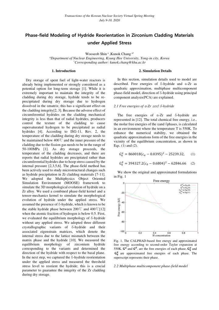
quadratic approximation, multiphase multicomponent phase-field model, direction of δ-hydride using principal component analysis(PCA) are explained. 2.1 Free energies of α-Zr and δ-hydride The free energies of α-Zr and δ-hydride are represented in [12]. The total chemical free energy, i.e., the molar free energies of the αand δphases, is calculated in an environment where the temperature T is 550K. To enhance the numerical stability, we obtained the quadratic approximations form of the free energies in the vicinity of the equilibrium concentration, as shown in

  • Eqs. (1) and (2).

𝐻𝑟

𝛽 = 860018(𝑑𝛽 − 0.0395)2 − 25239.32, (1)

𝐻𝑟

𝜀 = 394327.2(𝑑𝜀 − 0.6804)2 − 62846.66 (2)

We show the original and approximated formulations in Fig. 1

  • Fig. 1. The CALPHAD-based free energy and approximated

free energy according to second-order Taylor expansion at

  • 550K. 𝐇𝜷 and 𝑯𝜺, are the free energies of each phase, 𝐇𝒓

𝜷 and

𝐇𝒓

𝜺 are approximated free energies of each phase. The

superscript represents their phase.

2.2 Multiphase multicomponent phase-field model

Transactions of the Korean Nuclear Society Virtual Spring Meeting July 9-10, 2020

slide-2
SLIDE 2

Cahn-Hilliard equation [13] with respect to the concentration of hydrogen and the Allen-Cahn equation [14] with respect to the structural parameter η as follow:

∂c(r, t) 𝜖𝑢 = ∇ ⋅ [M∇ (∂g𝑑ℎ𝑓𝑛 𝜖𝑑 )] , (3) ∂η 𝜖𝑢 = −L (∂g𝑑ℎ𝑓𝑛 𝜖𝜃 − κ𝜃

2∇2η + ∂E𝑓𝑚𝑏𝑡

𝜖𝜃 ), (4)

where M is the hydrogen mobility; L is the kinetic coefficient of η; g𝑑ℎ𝑓𝑛 is the bulk free energy density; E𝑓𝑚𝑏𝑡 is the elastic strain energy; κ𝜃 is the gradient energy coefficient associated with an interface energy. The constraint equations for the concentrations are the mass conservation equation and the pointwise equality equation of the chemical potentials of the phases. The KKS model implemented in this study is a two-phase model with concentration variables c𝛽 and c𝜀 , in addition to the global concentration c following Eq.(5). c𝛽 and c𝜀 are the molar fractions of atomic H in the matrix and δ-hydride,respectively. c(r, t) = (1 − ℎ(𝜃))𝑑𝛽 + ℎ(𝜃)𝑑𝜀 (5) The free energies of α and δ are functions of the solute concentrations of each phase. The pointwise equality of the diffusion potentials of each phase is shown in Eq. (6).

∂G𝛽 𝜖𝑑𝛽 = 𝜖𝐻𝜀 𝜖𝑑𝜀 (6)

2.3 Elastic strain energy The elastic strain energy was computed using the Voigh-Taylor scheme [15]. When δ-hydride precipitates in α-Zr, the elastic strain energy is derived from the structural difference between δ-hydride and α-Zr. δ- hydride is an interstitial solid solution having a fcc structure and α-Zr is an interstitial solid solution having an hcp structure. The elastic strain energy E𝑓𝑚𝑏𝑡 can be calculated as shown in Eqs. (7) - (10) [16].

E𝑓𝑚𝑏𝑡 = (1 − ℎ(𝜃))𝐹𝑓𝑚𝑏𝑡

𝛽

+ h(η)𝐹𝑓𝑚𝑏𝑡

𝜀

(7) E𝑓𝑚𝑏𝑡

𝛽

=

1 2 𝐷𝑗𝑘𝑙𝑚 𝛽 ϵ𝑗𝑘 𝑓𝑚,𝛽ϵ𝑙𝑚 𝑓𝑚,𝛽 = 1 2 𝐷𝑗𝑘𝑙𝑚 𝛽 𝜗𝑗𝑘𝜗𝑙𝑚 (8)

E𝑓𝑚𝑏𝑡

𝜀

=

1 2 𝐷𝑗𝑘𝑙𝑚 𝜀

ϵ𝑗𝑘

𝑓𝑚,𝜀ϵ𝑙𝑚 𝑓𝑚,𝜀 = 1 2 𝐷𝑗𝑘𝑙𝑚 𝛽 (𝜗𝑗𝑘 − 𝜗𝑗𝑘 00)(𝜗𝑙𝑚 − 𝜗𝑙𝑚 00) (9)

ϵij =

1 2 [ 𝜖𝑣𝑗(𝑠) 𝜖𝑦𝑗 + 𝜖𝑣𝑘(𝑠) 𝜖𝑦𝑘 ] (10)

Here, Cijkl

𝛽 is the elastic modulus tensor of the α-Zr

matrix, C𝑗𝑘𝑙𝑚

𝜀

is the elastic modulus tensor of δ-hydride; ϵ𝑗𝑘

el is the elastic tensor; ϵij is the eigenstrain tensor[16].

To solve the mechanical equilibrium equation in Eq. (11), the stress was interpolated as a function of the structural parameter η , assuming the quasi-steady approximation [15] with ∇ ⋅ σij = ∇ ⋅ [ (1 − h(η))σij

𝛽 + h(η)σkl 𝜀 ] = 0 (11)

where σ𝑗𝑘

𝛽 = Cijkl 𝛽 ϵij 𝑓𝑚, σ𝑗𝑘 𝛽 is the total stress implemented

  • n the α-Zr matrix and σ𝑗𝑘

𝜀 = Cijkl 𝜀 𝜗𝑗𝑘 𝑓𝑚 , σ𝑗𝑘 𝜀 is the total

stress implemented on the δ-hydride. To investigate the effect of the applied stress in the morphological and directional transition of δ-hydride, the applied stress σapp was implemented via a displacement boundary condition. 2.4 Measurement of direction of the hydride To determine the direction of the δ-hydride and its angle to the z-axis after reorientation, we performed a principal component analysis(PCA) [17]. Voxels with hydrogen concentrations greater than 0.1 were assumed to be belong to δ -hydride. Then, we calculated the mean values of the x-, y-, and z-coordinates, and we constructed the covariance matrix (A), which is obtained by calculating the differences in the coordinates between each position and the mean values. We obtained the eigenvalue λ and its associated eigenvector: Au = λu (12) (A − λI)𝑣 = 0 (13) Where A is a covariance matrix of the data, λ is a scalar called the eigenvalue associated with the eigenvector and u is the eigenvector of the covariance matrix A maximizing the variance in the voxels of δ-

  • hydride. We assume that the hydride direction u, which

is the eigenvector, corresponds to the maximum value of the eigenvalue.

  • Fig. 2. The principal component u of 𝛆 -hydride after

reorientation and the angle between z-axis and u

  • 3. Results

We placed a spherical hydride at the center of the simulation cell and found that the equilibrium morphology of the hydride was platelet shaped for three

Transactions of the Korean Nuclear Society Virtual Spring Meeting July 9-10, 2020

slide-3
SLIDE 3

different crystallographic variants in Fig. 3. Which is consistent with previous experimental observations [2, 18, 19].

  • Fig. 3. Growth of a 𝛆-hydride within 𝛃-Zr at a temperature of

T=550K in three dimensions. The images show the hydride at steady state with different variants (a) variant 1 [𝟐𝟐𝟑 ̅𝟏]; (b) variant 2 [𝟐 ̅𝟑𝟐 ̅𝟏]; and (c) variant 3 [𝟑 ̅𝟐𝟐𝟏]. The hydrogen concentrations are shown by the colors figures.

We applied an external stress in the form of a displacement[xxx]. We applied the displacement boundary condition along the y-direction, and we measured the stress level without a hydride to convert the displacement to an applied stress. We tested two different 3D simulation cell sizes, 𝟒𝟑𝟒𝒐𝒏𝟒, 𝟓𝟏𝟒𝒐𝒏𝟒 and we plotted the correlation between the applied stress level and 𝛊𝐴, which is the angle between the hydride direction measured by PCA and the [001] direction in Fig. 4.

  • Fig. 4. The angle between the hydride direction and the [001]
  • direction. 𝛊𝐴 is the angle and 𝛕∗ is the non-dimensionalized

applied stress on the system boundary.

We clearly observed the threshold stress, which is the stress level when the direction of the hydride begins to rotate and we found that this value depended on the simulation cell size (Fig. 4). We measured 𝛖𝐳𝐴 in the cases when comparable tensile stresses 𝛕𝐳𝐳 were comparable, the tensile stress level decreased as the simulation cell size increased. In

  • Fig. 5, the 𝛕𝐳𝐳 values are 22.482 and 21.250, which are

comparable, however, we found that the high 𝛖𝐲𝐴 zone is notably thicker in the 𝟓𝟏𝟒𝒐𝒏𝟒 case compared to the 𝟒𝟑𝟒𝒐𝒏𝟒 case. When the simulation cell size is small, which means that a high mechanical constraint is applied, the hydride is more difficult to rotate.

  • Fig. 5. Tensile stress 𝛕𝐳𝐳 and shear stress 𝛖𝐳𝐴 when the

simulations cell size are 𝟒𝟑𝟒𝐨𝐧𝟒 and 𝟓𝟏𝟒𝒐𝒏𝟒; (a) tensile stress level in the 𝟒𝟑𝟒𝒐𝒏𝟒 system, (b) the tensile stress level in the 𝟓𝟏𝟒𝒐𝒏𝟒 system, (c) the shear stress level in the 𝟒𝟑𝟒𝒐𝒏𝟒 system, and (d) the shear stress level in the 𝟓𝟏𝟒𝒐𝒏𝟒 𝒕𝒛𝒕𝒖𝒇𝒏.

The constraint effect of this simulation cell size is expected to disappear when the simulation cell size is increased above a certain level. However, because the 𝟓𝟏𝟒𝐨𝐧𝟒 simulation takes more than a week to run even with parallel computing on 32 CPU cores (64 threads) (AMD Ryzen Threadripper 3970X), we did not perform an additional convergence test. As shown in Fig. 4, 𝛊𝐴 does not evolve when the applied stress is below the threshold level. For example, when the simulation cell size is 𝟒𝟑𝟒𝒐𝒏𝟒, 𝛊𝐴 is mostly invariant as 𝛕∗ increases until 𝛕∗ is 2.792. This can be categorized as the invariant regime. The next regime is the transient regime. When 𝛕∗= 3.350, even though 𝛊𝐴 is smaller than the saturated value, which is approximately 57◦, it is rotated by approximately 45◦. In addition, when 𝛕∗= 4.466 and 5.583, 𝛊𝐴 is larger than the value of 𝛊𝐴 when 𝛕∗>6. Finally, 𝛊𝐴 becomes mostly saturated with respect to 𝛕∗ when the applied stress level is larger than 6.670 when the simulation cell size is 𝟒𝟑𝟒𝒐𝒏𝟒; we call this the saturated regime.

  • 4. Conclusions and Future Work

Phase-field kernels and tensor-mechanics kernels in the MOOSE framework were used to model changes in the δ-hydride microstructure of α-Zr. Initial spherical nuclei were shown to evolve into platelet shaped hydride, as experimentally observed in previous studies even when we did not apply an external stress. In the presence

  • f an external applied stress, the direction of the hydride

did not change when the applied stress level was below a threshold level. However, in agreement with the conventional understanding, the hydride gradually turned toward a certain direction, when the stress condition was above a certain level; then, additional rotation in the direction of the hydride was no longer

  • bserved. Because the stress state in actual cladding is

more complex than the assumptions used in this study

Transactions of the Korean Nuclear Society Virtual Spring Meeting July 9-10, 2020

slide-4
SLIDE 4

(where only σyy was non-zero), further studies are required to investigate hydride morphological evolution under various stress states, that have a position dependence in the cladding tube. REFERENCES

[1] D. Kook, J. Choi, J. Kim, Y. Kim, Review of spent fuel integrity evaluation for dry storage, Nuclear engineering and technology 45 (1) (2013) 115-124 (2013). [2] K. B. Colas, A. T. Motta, M. R. Daymond, J. D. Almer, Effect of thermo-mechanical cycling on zirconium hydride reorientation studied in situ with synchrotron x-ray diffraction, Journal of Nuclear Materials 440 (1-3) (2013) 586–595 (2013). [3] K. Sakamoto, M. Nakatsuka, Stress reorientation of hydrides in recrystallized zircaloy-2 sheet, Journal of Nuclear Science and Technology 43 (9) (2006) 1136-1141 (2006). [4] D. Pickman, Properties of zircaloy cladding, Nuclear Engineering and Design 21 (2) (1972) 212-236 (1972), [5] H.-J. Cha, J.-J. Won, K.-N. Jang, J.-H. An, K.-T. Kim, Tensile hoop stress-, hydrogen content-and cooling rate- dependent hydride reorientation behaviors of zr alloy cladding tubes, Journal of Nuclear Materials 464 (2015) 53-60 (2015). [6] J.-S. Kim, Y.-J. Kim, D.-H. Kook, Y.-S. Kim, A study on hydride reorientation of zircaloy-4 cladding tube under stress, Journal of Nuclear Materials 456 (2015) 246-252 (2015). [7] Z. Xiao, M. Hao, X. Guo, G. Tang, S.-Q. Shi, A quantitative phase field model for hydride precipitation in zirconium alloys: Part ii. Modeling of temperature dependent hydride precipitation, Journal of Nuclear Materials 459 (2015) 330-338 (2015). [8] T. W. Heo, K. B. Colas, A. T. Motta, L.-Q. Chen, A phase- field model for hydride formation in polycrystalline metals: Application to δ-hydride in zirconium alloys, Acta Materialia 181 (2019) 262-277 (2019). [9] J. Bair, M. A. Zaeem, M. Tonks, A phase-field model to study the effects of temperature change on shape evolution of γ-hydrides in zirconium, Journal of Physics D: Applied Physics 49 (40) (2016) 405302(2016). [10] G. Han, Y. Zhao, C. Zhou, D.-Y. Lin, X. Y. Zhu, J. Zhang,

  • S. Hu, H. F. Song, Phase-field modeling of stacking structure

formation and transition of δ-hydride precipitates in zirconium, Acta Materialia 165 (2019) 528-546 (2019). [11] A. Jokisaari, K. Thornton, General method for incorporating calphad free energies of mixing into phase field models: Application to the α -zirconium/ δ -hydride system, Calphad 51 (2015) 334-343 (2015). [12] N. Dupin, I. Ansara, C. Servant, C. Toffolon, C. Lemaignan, J. Brachet, A thermodynamic database for zirconium alloys, Journal of Nuclear Materials 275 (3) (1999) 287-295 (1999). [13] J. W. Cahn, J. E. Hilliard, Free energy of a nonuniform

  • system. i. interfacial free energy, The Journal of Chemical

Physics 28 (2) (1958) 258-267 (1958) [14] S. M. Allen, J. W. Cahn, A microscopic theory for antiphase boundary motion and its application to antiphase domain coarsening, Acta Metallurgica 27 (6) (1979) 1085-1095 (1979) [15] L. K. Aagesen, D. Schwen, K. Ahmed, M. R. Tonks, Quantifying elastic energy effects on interfacial energy in the kim-kim-suzuki phase-field model with different interpolation schemes, Computational Materials Science 140 (2017) 10-21 (2017). [16] A. M. Jokisaari, Multiphysics phase field modeling of hydrogen diffusion and δ-hydride precipitation in α-zirconium., Ph.D. thesis, University of Michigan (2016). [17] H. Abdi, L. J. Williams, Principal component analysis, Wiley interdisciplinary reviews: computational statistics 2 (4) (2010) 433-459 (2010). [18] J. Bailey, Electron microscope observations on the precipitation of zirconium hydride in zirconium, Acta metallurgica 11 (4) (1963) 267-280 (1963) [19] D. Westlake, The habit planes of zirconium hydride in zirconium and zircaloy, Journal of Nuclear Materials 26 (2) (1968) 208-216 (1968). [20] J.-l. Lin, B. J. Heuser, Modeling hydrogen solvus in zirconium solution by the mesoscale phase-field modeling code hyrax, Computational Materials Science 156 (2019) 224–231 (2019). Transactions of the Korean Nuclear Society Virtual Spring Meeting July 9-10, 2020