PID Controller - Basic Design 1. Let input to controller by E ( z ) - - PowerPoint PPT Presentation

pid controller basic design
SMART_READER_LITE
LIVE PREVIEW

PID Controller - Basic Design 1. Let input to controller by E ( z ) - - PowerPoint PPT Presentation

PID Controller - Basic Design 1. Let input to controller by E ( z ) and output from it be U ( z ) . If gain is K , i is integral time and d is derivative time, t e ( t ) + 1 de ( t ) u ( t ) = K e ( t ) dt + d i dt 0 U (


slide-1
SLIDE 1

1.

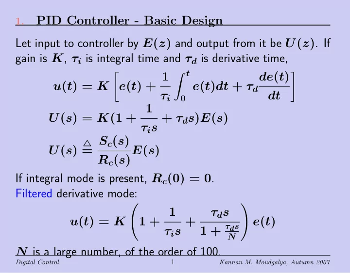
PID Controller - Basic Design Let input to controller by E(z) and output from it be U(z). If gain is K, τi is integral time and τd is derivative time, u(t) = K

  • e(t) + 1

τi t e(t)dt + τd de(t) dt

  • U(s) = K(1 + 1

τis + τds)E(s) U(s)

= Sc(s) Rc(s)E(s) If integral mode is present, Rc(0) = 0. Filtered derivative mode: u(t) = K

  • 1 + 1

τis + τds 1 + τds

N

  • e(t)

N is a large number, of the order of 100.

Digital Control

1

Kannan M. Moudgalya, Autumn 2007

slide-2
SLIDE 2

2.

Derivative Mode

  • Integral Mode using Tustin/Bilinear: 1

s ↔ Ts 2 z + 1 z − 1

  • Derivative Mode

– Reciprocal results in wildly oscillating control effort. Rect- angular approximation solves this problem. – Backward difference formula: 1 s ↔ Ts z z − 1 – Forward difference formula: 1 s ↔ Ts z − 1 – Both are used

  • Rectangular approximation is used for integral mode as well

Digital Control

2

Kannan M. Moudgalya, Autumn 2007

slide-3
SLIDE 3

3.

2-DOF Controller

y Tc Rc G = B A Sc Rc r u −

u = Tc Rc r − Sc Rc y It is easy to arrive at the following relation between r and y. y = Tc Rc B/A 1 + BSc/ARc r = BTc ARc + BSc r Error e, given by r − y is given by e =

  • 1 −

BTc ARc + BSc

  • r = ARc + BSc − BTc

ARc + BSc r

Digital Control

3

Kannan M. Moudgalya, Autumn 2007

slide-4
SLIDE 4

4.

Offset-Free Tracking of Steps with Integral Recall expression for E, showing the dependence on z: E(z) = A(z)Rc(z) + B(z)Sc(z) − B(z)Tc(z) A(z)Rc(z) + B(z)Sc(z) R(z)

lim

n→∞ e(n) = lim z→1

z − 1 z A(z)Rc(z) + B(z)Sc(z) − B(z)Tc(z) A(z)Rc(z) + B(z)Sc(z) z z − 1

Because the controller has an integral action, Rc(1) = 0: e(∞) = Sc(z) − Tc(z) Sc(z)

  • z=1

= Sc(1) − Tc(1) Sc(1) This condition can be satisfied if one of the following is met: Tc = Sc Tc = Sc(1) Tc(1) = Sc(1)

Digital Control

4

Kannan M. Moudgalya, Autumn 2007

slide-5
SLIDE 5

5.

Tc = Sc: Offset-Free Tracking with Integral u = Tc Rc r − Sc Rc y

y Tc Rc G = B A Sc Rc r u −

How do we obtain the standard configuration, with e = r − y?

r − G(z) = B A Gc(z) = Sc Rc u e y v

Answer: Tc = Sc. Substituting this in the above equation, u = Sc Rc (r − y) = Sc Rc e = Tc Rc e Tc = Sc ensures offset free tracking!

Digital Control

5

Kannan M. Moudgalya, Autumn 2007

slide-6
SLIDE 6

6.

Tc = Sc: Offset-Free Tracking with Integral

  • Recall: Tc = Sc results in offset free tracking and

u = Sc Rc e = Tc Rc e

  • Precisely what is available from standard PID controller:

U(s) = K(1 + 1 τis + τds)E(s)

  • Recall approximations:

Integral: 1 s ↔ Ts 2 z + 1 z − 1, Derivative: s ↔ 1 Ts z − 1 z

  • Substituting,

U(z) = K

  • 1 + 1

τi Ts 2 z + 1 z − 1 + τd Ts z − 1 z

  • E(z)

Digital Control

6

Kannan M. Moudgalya, Autumn 2007

slide-7
SLIDE 7

7.

Tc = Sc: Offset-Free Tracking with Integral Recall from the previous slide: U(z) = K

  • 1 + 1

τi Ts 2 z + 1 z − 1 + τd Ts z − 1 z

  • E(z)

Cross multiplying and taking inverse Z-transform, obtain u(n + 1) = u(n) + s0e(n + 1) + s1e(n) + s2e(n − 1) s0 = K

  • 1 + Ts

2τi + τd Ts

  • s1 = K
  • −1 + Ts

2τi − 2τd Ts

  • s2 = K τd

Ts Smooth transfer from manual to auto mode. Bumpless transfer.

Digital Control

7

Kannan M. Moudgalya, Autumn 2007

slide-8
SLIDE 8

8.

PID Controller with Filtering and Tc = Sc Recall filtered derivative mode: u(t) = K

  • 1 + 1

τis + τds 1 + τds

N

  • e(t)

Use backward approximation 1

s ↔ Ts z z−1 = Ts 1 1−z−1 for all:

1 1 + τds/N ↔ −NTs τd r1 1 + r1z−1 where r1 = − τd/N τd/N + Ts Control law becomes: Sc Rc = K

  • 1 + Ts

τi 1 1 − z−1 − Nr1(1 − z−1) 1 + r1z−1

  • Digital Control

8

Kannan M. Moudgalya, Autumn 2007

slide-9
SLIDE 9

9.

PID Controller with Filtering and Tc = Sc

Sc Rc = K

  • 1 + Ts

τi 1 1 − z−1 − Nr1(1 − z−1) 1 + r1z−1

  • = K(1 − z−1)(1 + r1z−1) + Ts/τi(1 + r1z−1) − Nr1(1 − z−1)2

(1 − z−1)(1 + r1z−1)

Comparing the denominator and the numerator, we obtain Sc(z) = s0 + s1z−1 + s2z−2 Rc(z) = (1 − z−1)(1 + r1z−1) with s0 = K

  • 1 + Ts

τi − Nr1

  • s1 = K
  • r1
  • 1 + Ts

τi + 2N

  • − 1
  • s2 = −Kr1(1 + N)

Digital Control

9

Kannan M. Moudgalya, Autumn 2007

slide-10
SLIDE 10

10.

PID Controller with Filtering and Tc = Sc Recall Sc(z) = s0 + s1z−1 + s2z−2 Rc(z) = (1 − z−1)(1 + r1z−1) PID control law is given by u(n) = Sc Rc e(n) = s0 + s1z−1 + s2z−2 (1 − z−1)(1 + r1z−1)e(n) Cross multiplying, we obtain the control law: (1 − z−1)(1 + r1z−1)u(n) = (s0 + s1z−1 + s2z−2)e(n) On introduction of filtering action in the derivative mode, we lose the useful property of bumpless control action.

Digital Control

10

Kannan M. Moudgalya, Autumn 2007

slide-11
SLIDE 11

11.

PD Controller with Filtering and Tc = Sc Recall Sc Rc = K

  • 1 + Ts

τi 1 1 − z−1 − Nr1(1 − z−1) 1 + r1z−1

  • Do not want integral mode. Delete second term:

Sc Rc = K

  • 1 − Nr1(1 − z−1)

1 + r1z−1

  • = K(1 − Nr1) + r1(1 + N)z−1

1 + r1z−1 Discrete time PD control law is given by (1 + r1z−1)u(n) = (s0 + s1z−1)e(n) where, s0 = K(1 − Nr1), s1 = Kr1(1 + N). Not in incremental form. No integral action.

Digital Control

11

Kannan M. Moudgalya, Autumn 2007

slide-12
SLIDE 12

12.

Setpoint, Derivative, Proportional Kicks

  • The standard PID control law has a shortcoming.
  • If there is a sudden change in the setpoint,

– both proportional and derivative modes will introduce large jumps in the control effort, known as setpoint kick. – The large change introduced by the derivative mode is known as derivative kick. – Proportional mode could also produce a large control ef- fort, known as proportional kick. – Both derivative and proportional kicks are generally not acceptable.

  • Solved in a feedback configuration, to be given in the next

slide.

Digital Control

12

Kannan M. Moudgalya, Autumn 2007

slide-13
SLIDE 13

13.

2-DOF PID Controller with no Setpoint Kicks Recall PID control law with filtered derivative action: u(t) = K

  • 1 + 1

τis + τds 1 + τds

N

  • e(t)

With e(t) = r(t) − y(t), it becomes, u(t) = K

  • 1 + 1

τis + τds 1 + τds

N

  • (r(t) − y(t))

To remove setpoint kick, propose the following control law: u(t) = K τis

  • 1 + τds

N

(r(t) − y(t)) − K

  • 1 +

τds 1 + τds

N

  • y(t)

Setpoint kick removed. The exact structure to be explained.

Digital Control

13

Kannan M. Moudgalya, Autumn 2007

slide-14
SLIDE 14

14.

2-DOF PID Controller with no Setpoint Kicks Recall the control law from previous slide: u(t) = K τis

  • 1 + τds

N

(r(t) − y(t)) − K

  • 1 +

τds 1 + τds

N

  • y(t)

Grouping the terms involving y(t), we obtain

u(t) = K τis

  • 1 + τds

N

r(t) − K

  • 1 +

τds 1 + τds

N

+ 1 τis

  • 1 + τds

N

  • y(t)

This can be simplified as u = K τis(1 + τds/N)r − K

  • 1 +

τiτds2 + 1 τis(1 + τds/N)

  • y

In the form u = Tc

Rcr − Sc Rcy, with Tc(0) = Sc(0) = K

Digital Control

14

Kannan M. Moudgalya, Autumn 2007

slide-15
SLIDE 15

15.

2-DOF PID Controller with no Setpoint Kicks Recall the control law that avoids setpoint kicks: u(t) = K τis

  • 1 + τds

N

(r(t) − y(t)) − K

  • 1 +

τds 1 + τds

N

  • y(t)

This can be implemented as,

y G K τis(1 + τds/N)

r u v

K

  • 1 +

τds 1 + τds/N

Please read the rest of Chapter 8.

Digital Control

15

Kannan M. Moudgalya, Autumn 2007