Previous Lecture Todays Lecture Slides for Lecture 33 ENEL 353: - - PowerPoint PPT Presentation

previous lecture today s lecture slides for lecture 33
SMART_READER_LITE
LIVE PREVIEW

Previous Lecture Todays Lecture Slides for Lecture 33 ENEL 353: - - PowerPoint PPT Presentation

ENEL 353 F13 Section 02 Slides for Lecture 33 slide 2/23 ENEL 353 F13 Section 02 Slides for Lecture 33 slide 3/23 Previous Lecture Todays Lecture Slides for Lecture 33 ENEL 353: Digital Circuits Fall 2013 Term Completion of a timing


slide-1
SLIDE 1

Slides for Lecture 33

ENEL 353: Digital Circuits — Fall 2013 Term Steve Norman, PhD, PEng Electrical & Computer Engineering Schulich School of Engineering University of Calgary 27 November, 2013 ENEL 353 F13 Section 02 Slides for Lecture 33 slide 2/23

Previous Lecture

Completion of a timing analysis example. Introduction to clock skew. Adjustment of setup and hold time constraint inequalities to account for clock skew. What can happen when setup and hold time constraints are violated? Introduction to metastability. ENEL 353 F13 Section 02 Slides for Lecture 33 slide 3/23

Today’s Lecture

The problem of asynchronous inputs to synchronous systems; solution with synchronizer circuits. Some insight into where metastability and setup times come from. Related reading in Harris & Harris: Sections 3.4.4–3.4.5. ENEL 353 F13 Section 02 Slides for Lecture 33 slide 4/23

Preventing metastability from causing circuit failure

A single DFF going metastable for a fraction of a clock cycle may cause a synchronous system to behave incorrectly for a much longer time period, and may even cause the system to freeze completely. One essential step in reducing the risk of problems is, as we’ve just seen, careful timing analysis
  • f paths like this . . .
C L CLK But what about system inputs? Edges on inputs can have completely unpredictable timing relative to edges on the the system clock! ENEL 353 F13 Section 02 Slides for Lecture 33 slide 5/23

Examples of asynchronous inputs

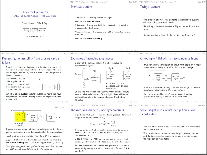
In each of the systems below, A is what is called an asynchronous input . . . button A synchronous system CLK A CLK1 system 1 CLK2 system 2 synchro- nous synchro- nous CLK1 and CLK2 are unrelated, with different frequencies. On the left, the system can’t control when a human might press or release the button. On the right, there will be no predictable relationship between edges on A and edges
  • n CLK2.
ENEL 353 F13 Section 02 Slides for Lecture 33 slide 6/23

An example FSM with an asynchronous input

If we don’t know anything at all about when edges on A might appear relative to edges on CLK, this is a bad design . . . next state logic
  • utput
logic Y A CLK Why is it impossible to design the next state logic to prevent disastrous metastability in the state register? To greatly reduce the risk, A can be passed though a synchronizer circuit, as shown on the next slide . . . slide 7/23 next state logic
  • utput
logic Y n2 n1 A FF2 FF1 synchronizer circuit CLK Suppose the next state logic has been designed so that its tpd and tcd meet setup and hold constraints for the state register. Recall that tres is the resolution time for a DFF or register. Suppose that a detailed transistor-level model says that it is extremely unlikely that it will ever happen that tres > 0.5TC. Let’s give an approximate, qualitative argument that there is very little risk of metastability in the state register. ENEL 353 F13 Section 02 Slides for Lecture 33 slide 8/23

Detailed analysis of tres and synchronizers

In Sections 3.4.4–3.4.6, Harris and Harris present a formula for the probability distribution of tres: P(tres > t) = T0 TC exp −t τ
  • They go on to use that probability distribution to derive a
formula for MTBF (mean time between failures) of synchronizer circuits. In ENEL 353 in Fall 2013, we are not going to cover that material, and you will not be tested on it on the final exam. You are expected to understand the qualitative ideas about metastability and synchronizers presented in Sections 3.4.4 and 3.4.5. ENEL 353 F13 Section 02 Slides for Lecture 33 slide 9/23

Some insight into circuits, setup times, and metastability

The rest of the slides in this lecture are not exam material in ENEL 353 in Fall 2013. They are intended to provide some insight into why latches and flip-flops must have setup times, and why latches and flip-flops can go metastable.
slide-2
SLIDE 2 ENEL 353 F13 Section 02 Slides for Lecture 33 slide 10/23

Static behaviour of CMOS NOT, NOR, and NAND gates

If we slowly vary the voltage at A in each of the circuits below, and measure the voltage at Y as we go, we’ll see an input/output relationship that looks something like the graph sketched to the right. A Y A A Y Y VDD voltage at A voltage at Y VDD ENEL 353 F13 Section 02 Slides for Lecture 33 slide 11/23

Static solutions for some bistable circuits

gate 1 1 1 gate 1 gate 2 gate 2 gate 1 Q Q QN Q QN QN gate 2 For each of the circuits, there are three static conditions that satisfy input/output voltage relationships for both gates . . . gate 2 gate 1 VDD voltage at Q VDD voltage at QN ENEL 353 F13 Section 02 Slides for Lecture 33 slide 12/23

Static solutions for bistable circuits, continued

gate 2 gate 1 VDD voltage at Q VDD voltage at QN The upper-left and lower-right solutions are the stable solutions predicted by Boolean algebra: (Q, QN) = (0, 1) and (Q, QN) = (1, 0). Boolean algebra only works with 1’s and 0’s, so cannot predict the metastable solution in the middle of the graph. ENEL 353 F13 Section 02 Slides for Lecture 33 slide 13/23

Dynamic behaviour of bistable circuits

Static analysis shows us only what the possible solutions are when dV /dt = 0 for both gate outputs, and does not tell us how voltages might change as a function of time. Transistor physics and circuit theory, beyond what has been taught to year 2 ENEL and ENSF students, says . . . ◮ The static solutions that are identified by Boolean algebra are stable equilibrium points. If a bistable circuit is in
  • ne of its stable states, moderate amounts of electrical
noise will not move the state very far away from that stable state. ◮ The metastable state of a bistable circuit is an unstable equilibrium point. A very tiny amount of electrical noise will rapidly drive the circuit from there into one or the other of its stable states. ENEL 353 F13 Section 02 Slides for Lecture 33 slide 14/23

Metastability in a D flip-flop

We studied this design in lectures and also in Lab 4. It’s not how D flip-flops are constructed in most modern integrated circuits, but the design is relatively easy to understand. master D latch slave D latch RM SM CLK D QM QNM QFF Reminder: Because CLK passes through a NOT gate before entering the master latch, the master latch is transparent when CLK is LOW. ENEL 353 F13 Section 02 Slides for Lecture 33 slide 15/23 Let’s look at what happens in the master latch when there is an edge on D just before a rising edge on CLK. RM SM CLK D QM QNM CLK SM RM D In an ideal SR latch, (QM, QNM) will go to (1, 0) because of the pulse on SM. But in a real SR latch, the width of the pulse matters. A wide pulse will make the latch “do the right thing.” A very narrow pulse will not decrease the voltage at QNM very much, and the voltage at QM won’t change at all. (QM, QNM) will settle back to (0, 1). ENEL 353 F13 Section 02 Slides for Lecture 33 slide 16/23 RM SM CLK D QM QNM CLK SM RM D If the width of the pulse on SM is “perfectly wrong” the voltages at QM and QNM will both be near 0.5VDD when the pulse ends. That gives the pair of NOR gates a chance to go metastable! ENEL 353 F13 Section 02 Slides for Lecture 33 slide 17/23 Now let’s have another look at the slave latch . . . master D latch slave D latch RM SM CLK D QM QNM QFF When CLK is HIGH, the slave latch is supposed to be
  • transparent. But if QM ≈ 0.5VDD, both AND gates in the
slave have “forbidden zone” inputs, and we cannot rely on QFF to have any particular value. If it’s still true that QM ≈ 0.5VDD when CLK goes from HIGH to LOW, that could make the NOR gates in the slave go metastable. ENEL 353 F13 Section 02 Slides for Lecture 33 slide 18/23

Setup time in a modern DFF

Below is a D latch suitable for use as the master latch in a
  • DFF. Switches S1 and S2 are implemented in CMOS using
simple two-transistor devices called transmission gates. QM CLK D CLK S1 QNM CLK CLK S2 I1 I2 I3 n1 CLK S1 S2 latch condition LOW closed
  • pen
transparent HIGH
  • pen
closed
  • paque
slide-3
SLIDE 3 ENEL 353 F13 Section 02 Slides for Lecture 33 slide 19/23 QM CLK D CLK S1 QNM CLK CLK S2 I1 I2 I3 n1 When CLK is LOW, S1 is closed and S2 is open. I1 and I2 form a simple buffer. When CLK is HIGH, S1 is open and S2 is closed. I2 and I3 form a bistable circuit that can lock the state in either (QM, QNM) = (0, 1) or (QM, QNM) = (1, 0). ENEL 353 F13 Section 02 Slides for Lecture 33 slide 20/23 QM CLK D CLK S1 QNM CLK CLK S2 I1 I2 I3 n1 What happens if there is an edge on D, just before a rising edge on CLK that will break the connection though S1? I1 may not have enough time to drive node n1 to the correct voltage for D, with one of two possible bad outcomes: ◮ QM could fail to copy the new value of D. ◮ If the n1 voltage is “just wrong”, the bistable circuit made from I2 and I3 could go metastable. If the signal at D respects a setup time specification, then the above bad outcomes can’t happen. ENEL 353 F13 Section 02 Slides for Lecture 33 slide 21/23

Some connections to the textbook and other literature

, not , is the usual symbol for a transmission gate. CLK A B CLK CLK B A CLK On the left, A and B are connected when CLK is HIGH. On the right, A and B are connected when CLK is LOW. ENEL 353 F13 Section 02 Slides for Lecture 33 slide 22/23

More connections to the textbook and other literature

Here is the complete DFF design. Note that the inverting tristate buffers T1 and T2 are really just inverters followed by transmission gates. CLK D N1 CLK CLK CLK I1 I2 T1 I3 CLK CLK T2 CLK CLK I4 Q N2 Image is Figure 3.13 from Harris D. M. and Harris S. L., Digital Design and Computer Architecture, 2nd ed., c 2013, Elsevier, Inc. ENEL 353 F13 Section 02 Slides for Lecture 33 slide 23/23

What’s left in ENEL 353?

Definitely these two topics: ◮ Counters and shift registers (H&H Section 5.4). ◮ Memory arrays (H&H Section 5.5). As time permits, some or all of these topics: ◮ PLAs (H&H Section 5.6.1). ◮ Carry-lookahead adders (H&H Section 5.2.1). ◮ Subtractors (H&H Section 5.2.2).