Radix 2/10 System Leibniz 10-BIT Binary/Decimal Desktop Slide Rule - - PowerPoint PPT Presentation
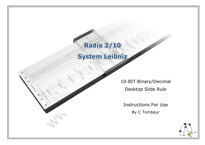
Radix 2/10 System Leibniz 10-BIT Binary/Decimal Desktop Slide Rule Instructions For Use By C Tombeur B inary numbers in their modern form using a system of ones and zeroes to represent values were invented by the philosopher and
B
inary numbers in their modern form using a system of ones and zeroes to represent values were invented by the philosopher and mathematician Wolfgang Leibniz, and described in his 1679 article Explication de l'Arithmétique Binaire. However, binary representations are at least four thousand years old; a binary system is evidenced in Chinese I Ching manuscripts from the first millennia BC, but it is thought to pre-date this by at least another thousand years. Today, since the dawn of the electronic age in the late 20th century, binary numbers have fully infiltrated and dramatically changed the way we live our lives. They are the hidden, fundamental language
- f the microprocessors that drive the everyday devices that we take for granted
today, from mobile phones and computers to freezers and toasters. Veagfafkjldfgkjrylonggshsghsfghwordprintedinwhite
- 1 -
Introduction
A Radix series slide rule is designed to be used for multiplication and division calculations in a similar way to a typical linear decimal slide rule, but using a different number base. In addition, a special set of equivalent scales allows values and answers to be simultaneously converted to, or read in, an alternative base system. The Radix 2/10 – System Leibniz is a logarithmic binary, 10-BIT precision, closed frame wooden desktop slide rule with decimal equivalent scales. The binary/decimal (base 2/base 10) combination of binary, primary calculating scales and decimal equivalent scales allows the user to quickly and easily perform binary multiplication and division, and number conversions between the two base systems. This guide provides a brief outline of the modern binary number system, as well as describing the key characteristics of this slide rule and how to perform the various operations, with examples.
Binary Number System
A number in any base can be stated using general notation, where b is the base, n is the number of digits and a is the digit value at position k from least to most significant digit, as: a1 x b0 + a2 x b1 + … + an x b(n-1)
- r
∑ 𝑏𝑙𝑐𝑙−1
𝑜 𝑙=1
e.g. The 6-digit decimal number 142857 comprises 7x100 + 5x101 + 8x10² + 2x10³ + 4x10⁴ + 1x10⁵ Numbers are made up of a string of the digits available to the base, where each digit to the left of the point is an order of magnitude greater than the last, from least to most significant digit. The number of available digits determines the order of magnitude and characterises the base. In decimal (base 10) there are 10 digits available; 0, 1, 2, 3, 4, 5, 6, 7, 8 and 9. The order of magnitude is therefore 10, with the digits successively to the left of the point representing units, tens, hundreds, thousands and so on. Each digit represent the amount of the magnitude present in the number.
- 2 -
Binary, or base 2, is the simplest of all bases in that numbers are made up using the two binary digits, or BITs, ‘0’ and ‘1’. The order of magnitude is 2, so the BITs successively to the left of the point represent units, twos, fours, eights, sixteens and so
- n from least to most significant BIT. A ‘1’ BIT
indicates the order of magnitude is present in the number, and a ‘0’ BIT that it is not. Table 1 shows some decimal numbers with their binary equivalents. It can be seen that binary numbers quickly become very long compared to their decimal equivalents. For example, the base 10 2-digit number 99 is 1100011 in base 2, 7-BITs long. Conversions between binary and decimal numbers are relatively simple but laborious. Using the above algorithm it can be seen that the binary number 1011 comprises 1x20 + 1x21 + 0x22 + 1x23 = 1x0 + 1x2 + 0x4 + 1x8 = 11 in decimal. Simple processes based on the algorithm enable conversion between binary and decimal numbers. A decimal number can be converted to binary by successively dividing it by 2 until the quotient becomes zero. The remainder of each division becomes the next least significant BIT (Table 2). The process is reversed to convert a binary number to decimal. Each BIT from most to least significant BIT is added to double the previous value, starting with zero (Table 3). Mathematical operations in binary are performed in a similar way to decimal, but are considerably more laborious. The Radix 2/10 simplifies conversion between the binary and decimal number systems, and multiplication and division operations.
DECIMAL BINARY Sig.: most least Sig.: most least digits: 3 2 1 BITs: 7 6 5 4 3 2 1 100's 10's 1's 64's 32's 16's 8's 4's 2's 1's 1 1 2 1 3 1 1 4 1 … … 9 1 1 1 1 1 1 1 1 1 1 1 2 1 1 … … 9 9 1 1 1 1 1 1 1 1 1 1 1 1 1 1 … … Table 1: Decimal numbers and their binary equivalents
- 3 -
DECIMAL 11 BINARY divided by 2 = 5 remainder 1 (read down) 1 + 2 x 0 = 1 divided by 2 = 2 remainder 1 + 2 x 1 = 2 divided by 2 = 1 remainder 0 (read up) 1 + 2 x 2 = 5 divided by 2 = remainder 1 BINARY 1 + 2 x 5 = 11 DECIMAL Table 2: Converting decimal 11 to binary Table 3: Converting binary 1011 to decimal
Layout and Scales
The slide rule features a pair of logarithmic binary primary scales and a pair of decimal equivalent scales, and a hairline cursor to assist in calculations. The binary scales BIN1 and BIN2 are positioned on the upper rail of the stock above the slide and on the adjacent upper half of the slide respectively, with the decimal scales DEC1 and DEC2on the lower half of the slide and the adjacent stock lower rail respectively (Figure 1). Each scale is 390mm long and comprises 10 BIT-lines, where each line represents a bit, and therefore a magnitude, in a binary number. The range of each scale is 1 to 1024 (10-BIT = 210 = 1024). The binary and decimal scales have the same fundamental logarithmic binary structure, but with formatting differences enabling them to be more easily read in their own base. For ease of understanding the binary scale concept, the scales can be thought of as decimal scales from 1 to 1024 broken into 10 lines at the powers of 2 and stacked, as can be clearly seen by studying the decimal equivalent scales. BIT-lines of the BIN1 and DEC1 scales are ordered from the most significant bit at the top to least significant bit at the bottom, whereas the BIT-lines of the BIN2 and DEC2 scales are in the reverse order (bottom to top, most to least significant bit). As such, the least significant BIT-line of each scale pair is adjacent. Figure 7: Scale layout
1 2 4 8 16 17 32 33 34 64 66 68 128 130 135 256 260 270 512 520 540 1 2 4 8 16 17 32 33 34 64 66 68 128 130 135 256 260 270 512 520 540
10 9 8 7 6 5 4 3 2 1 10 9 8 7 6 5 4 3 2 1 10 9 8 7 6 5 4 3 2 1 10 9 8 7 6 5 4 3 2 1 B I T B I T
SYSTEM LEIBNIZ Stock Top Rail Slide Stock Bottom Rail
BIN1 BIN2 DEC1 DEC2
- 4 -
Alternate BIT-lines are shaded blue on the BIN scales and red on the DEC scales for ease of tracking along the lines. BIT- lines on each scale are labelled in black from 1 (most significant) to 10 (least significant) at both ends, and on the right- hand end of the cursor pane, to aid conversions and help keep track of binary number lengths. Both pairs of scales have all integers from 1 to 1024 indicated with tick marks. The BIN scale tick marks indicate a ‘1’ bit value with a •. The DEC scales are labelled as follows: all 1-6 bit integers (1-63); even 7-BIT integers (64-127); 8-BIT integers divisible by 5 (128-255); 9-BIT integers divisible by 10 (256-511); 10-BIT integers divisible by 20 (512-1023). All powers of 2 at the start of each BIT-line are also labelled on the DEC scales. Integer labels are blue, except multiples
- f 10 which are red for ease of location.
The accuracy of the Radix 2/10 is limited to 10 bits, but operations on numbers with more than 10 bits can be performed in a similar way to a ‘standard’ slide rule..
Slide Rule Operation
The Radix 2/10 initially appears somewhat unfamiliar, complicated and confusing, so special care must be taken when reading the scales to avoid errors!
Reading the Scales and Conversions
Conversions between binary and decimal numbers effectively demonstrate how the scales are read. Either of the fixed scale pairs, BIN1/DEC2 on the stock or BIN2/DEC1 on the slide, can be used for conversions (Figure 7). Both pairs have their advantages; the scales on the slide are closer together, but the binary scale on the stock is slightly easier to read scanning downwards from most to least significant BIT. In either case the cursor hairline can be used to accurately track from one scale to the other. Note that while fractional BITs can be read on the binary scales, there are no tick marks for fractional components on the decimal scales, which should be estimated if required.
- 5 -
Building a Binary Number and Converting to Decimal The process for building a binary number is described here, however it is easier understand the process by following the example below. To convert a binary number to decimal, first construct the binary number on the BIN1 scale. Position the cursor hairline over the over the • at the left-hand index end of the 1-BIT line. This represents the most significant ‘1’ BIT of the binary number, any leading ‘0’ BITs are ignored. Consider each remaining BIT in the number. If the BIT is a ‘0’ move on to the next BIT. If the BIT is a ‘1’ move the cursor hairline to the right from its last position, along the corresponding BIT line until it reaches a •, and position the hairline over the supporting tick mark. When complete, note the number of integer BITs in the original binary number, ignoring any leading ‘0’ BITs. Refer to the DEC2 scale. On the BIT line corresponding to the noted number of integer BITs, read the decimal value at the tick mark under (or immediately to the left of) the cursor hairline. With practice it is possible to build the binary number moving the cursor only once across to its final position. If the binary number has more than 10-BITs, only the first 10-BITs from the first ‘1’ BIT can be built on the BIN scales. The equivalent value found on the 10-BIT line of the decimal scale must be factored by 2 for each additional BIT. Example 1: Convert 000010102 to base 10 (Figure 2). Set the cursor hairline over the left-hand index end of the BIN1 scale on the stock upper rail. Ignore the leading ‘0’ BITs. The • under the hairline on the 1-BIT line represents the 1st ‘1’ BIT in the binary number. The 2nd BIT is a ‘0’ and so is ignored. The 3rd BIT is a ‘1’, so move the cursor hairline to the right along the 3-BIT line of the BIN1 scale until a • is reached, and align the hairline over the supporting tick mark. The 4th and final BIT is a ‘0’ and so is also ignored. In the original binary number, 00001010, ignoring the leading ‘0’s there are 4 integer BITs. Refer now to the DEC2 scale on the stock lower rail. Under the cursor hairline on the 4-BIT line, read the answer of ‘10’. Therefore 10102 = 1010.
- 6 -
Decimal Number Location As described previously, decimal values on the equivalent scales are simply decimal integer labels on a logarithmic binary formatted scale. As such, the values in each BIT line are not organised as a range of a power of 10 as on a decimal slide rule, but rather as a range of a power of 2. This makes locating decimal values a little difficult at first. To assist in locating a value, labels for multiples of 10 are coloured red, and tick marks between these follow a conventional height hierarchy within the BIT line. Not all tick marks are labelled due to space limitations. A decimal value can be found by simply scanning the decimal scale and locating the value label and tick mark. If the required value is in a range where not all tick marks are labelled, the nearest value is located the appropriate tick mark counting to. Alternatively the left-hand end of the scale, where all of the powers of 2 are situated and labelled, can be studied to determine the BIT line that the required decimal value is in (Figure 6). The value label on the left-hand end of a BIT line indicates the start Figure 2: Converting 10102 to decimal (note BIN1 and DEC2 scales are shown adjacent).
1 2 4 5 8 9 10 16 17 18 19 20 32 33 34 35 36 37 38 39 40 64 66 68 70 72 74 76 78 80 128 130 135 140 145 150 155 160 256 260 270 280 290 300 310 320 512 520 540 560 580 600 620 640
10 9 8 7 6 5 4 3 2 1 10 9 8 7 6 5 4 3 2 1 B I T 1 1 Binary 10 Decimal
- 7 -
- f the range of the BIT line, with the left-hand end label on the next least significant BIT line indicating the end of the range.
Once the appropriate BIT line has been determined it is simply a matter of scanning along the BIT line, using value labels as a guide, to locate the tick mark representing the value. Numbers with a binary length of more than 10-BITs can be approximated, but the process is fiddly. First the range of the 10- BIT line of the DEC scale must be successively doubled until the required value is in the range; for example 11-BITs is 102410 to 204810, 12 BITs is 204810 to 409610 etc. Next the tick mark (or approximate) representing the value on the 10-BIT line is located by factoring up the value labels by the same amount; x2 for 11-BITs, x4 for 12-BITs etc. Converting a Decimal Number to Binary As with converting a binary number to decimal, it is easier to understand the process by following the example, but a general description is also given here. To convert a decimal number to binary, first locate the integer tick mark for the value on the DEC2 scale and position the cursor hairline over it (approximate any fractional component). Refer to the BIN1 scale. Scrutinise each of the BIT lines in turn starting from the 1-BIT line (most significant BIT), and ending at either the 10-BIT line or a BIT line where there is a • with a supporting tick mark directly under the hairline. For each BIT line, examine the range starting from underneath the hairline and ending to the left, either at the nearest • on the BIT line or a tick mark that crosses it and extends to a lower BIT line, whichever comes first. If there is a • with a tick mark directly under the hairline, this is both the start and end of the
- range. At the left end of each BIT line range scrutinised, if there is a • write a ‘1’ BIT or if there is a crossing tick mark write a
‘0’ BIT. When complete, note the number of the BIT line on the DEC2 scale in which the decimal number is located, this indicates the number of integer BITs in the equivalent binary number. Append trailing 0’s to the binary string written as required so that its length is equal to the number of integer BITs noted (or insert a point after the noted number of BITs if appropriate). The string of BITs written is the equivalent binary to the decimal number. Note that the 1st BIT will always be ‘1’ from the leftmost end of the 1-BIT line. For numbers with a binary length greater than 10-BITs, the value is located as described above and the first 10-BITs of the binary equivalent built. An appropriate number of ‘0’s are appended to make the binary length string correct.
- 8 -
Example 2: Convert 15410 to base 2 (Figure 3). Find the tick mark representing ‘154’ on the 8-BIT line of the DEC2 scale and position the cursor hairline over the tick mark. Refer to the BIN1 scale. Look at the 1-BIT line from beneath the hairline and to the left. There is no • under the hairline and no tick marks cross the BIT line before the • at the left-hand end, so write a ‘1’ as represented by the •. Next look at the 2-BIT line, there is no • under the hairline nor to the left before the tick mark from the 1st BIT crosses it at the left end, so write a ‘0’. Similarly, the 3-BIT line has no • under the hairline nor to the left before the tick mark from the 1st and 2nd BIT crosses it, so again write a ‘0’. The 4-BIT line is clear under the hairline, but there is a • to the left of it before a crossing tick mark, so write a ‘1’. The 5-BIT line has no • under the hairline or to the left before the tick mark from the 4th BIT crosses it, so write a ‘0’. The 6-BIT line, has nothing under the hairline but to the left of it there is a • before a crossing tick mark, so write a ‘1’. The 7- BIT line has a tick mark with a • under the hairline which means this is the last BIT line that needs to be scrutinised, so write a final ‘1’. The original value ‘154’ was found on the 8-BIT line of the DEC2 scale, meaning there are 8 integer BITs in the
1 2 4 5 8 9 10 16 17 18 19 20 32 33 34 35 36 37 38 39 40 64 66 68 70 72 74 76 78 80 128 130 135 140 145 150 155 160 256 260 270 280 290 300 310 320 512 520 540 560 580 600 620 640
10 9 8 7 6 5 4 3 2 1 10 9 8 7 6 5 4 3 2 1 B I T 1 1 Binary 154 Decimal 1 1
Figure 3: Converting 15410 to binary (note BIN1 and DEC2 scales are shown adjacent).
- 9 -
equivalent binary number. The binary string written is ‘1001011’ which has seven BITs, so an additional ‘0’ must be appended to give it the required 8 integer BITs. Therefore 15410 = 1010110 in binary.
Performing Multiplication and Division
Multiplication and division are performed in similar way to using the C and D scales on a standard logarithmic linear slide rule. Either of the binary primary, decimal equivalent or a combination of both scale pairs can be used for the calculations, and conversions read if required. When calculating with binary numbers greater than 10-BITs, only the first 10 BITs from the first ‘1’ BIT are used. The full count of BITs in each number are then used in the rules to determine the magnitude of the final answer. Answers with more than 10-BITs are padded with trailing ‘0’s to the required length. Decimal values and equivalents must be factored as described above if they are beyond the 10-BIT range. Multiplication To multiply two numbers, construct the first factor on the BIN1 scale (or locate it on the DEC2 scale) and position the cursor hairline over the tick
- mark. Move the slide so that either the left or right-hand index end is
underneath the hairline, as appropriate to enable the answer to be read in the stock scale range. Construct the second factor on the BIN2 scale (or locate it on the DEC1 scale) and position the hairline over the tick mark. Read the answer on the BIN1 scale (or the DEC2 scale), determining the number of integer BITs as follows: (No. of integer BITs in answer) = (No. integer BITs in 1st factor) + (No. of integer BITs in 2nd factor)
- (0 if slide protrudes to the left, or 1 if slide protrudes to the right).
Figure 4a: Constructing 1000112 (note BIN1 and DEC2 scales are shown adjacent).
1 2 4 8 16 17 32 33 34 35 64 66 68 70 128 130 135 140 256 260 270 280 512 520 540 560
10 9 8 7 6 5 4 3 2 1 10 9 8 7 6 5 4 3 2 1 B I T 1 Binary 35 Decimal 1 1
- 10 -
Example 3: What is 1000112 multiplied by 10012 in binary? What is the completed sum in decimal? Construct the 6-BIT first factor, 100011, on the BIN1 scale (Figure 4a). The • on the left-hand end of the 1-BIT line represents the 1st ‘1’ BIT in the factor, so position the cursor hairline over it. Ignore the 2nd, 3rd and 4th BITs as they are ‘0’s. The 5th BIT is a ‘1’ so move the hairline to the right along the 5-BIT line until it is over a •. The last (6th) BIT is also a ‘1’, so continue moving the hairline until it is over a • on the 6-BIT line. Refer to the 6-BIT line on the DEC2 scale and read the decimal equivalent of the first factor to be ‘35’. Figure 4b: Constructing 10012 on BIN2.
10 9 8 7 6 5 4 3 2 1 B I T 1 1 Binary 9 Decimal
1 2 4 8 9 16 17 18 32 33 34 35 36 64 66 68 70 72 128 130 135 140 145 256 260 270 280 290 512 520 540 560 580
10 9 8 7 6 5 4 3 2 1 10 9 8 7 6 5 4 3 2 1 B I T
- 11 -
Figure 4c: Reading answer 1001110112 on BIN1.
1 2 4 5 8 9 10 16 17 18 19 20 32 33 34 35 36 37 38 39 40 64 66 68 70 72 74 76 78 80 128 130 135 140 145 150 155 160 256 260 270 280 290 300 310 320 512 520 540 560 580 600 620 640
10 9 8 7 6 5 4 3 2 1 10 9 8 7 6 5 4 3 2 1 B I T
1 2 4 8 9 16 17 18 32 33 34 35 36 37 64 66 68 70 72 74 128 130 135 140 145 256 260 270 280 290 512 520 540 560 580
10 9 8 7 6 5 4 3 2 1 10 9 8 7 6 5 4 3 2 1 B I T 1 1 Binary 1 1 1 1 315 Decimal
- 12 -
Next, move the slide so that the left-hand index end is under the hairline (Figure 4b). Now construct the second factor, 1001,
- n the BIN2 scale. The • on the 1-BIT line under the hairline represents the 1st ‘1’ BIT. The 2nd and 3rd BITs can be ignored as
they are ‘0’s. The 4th (last) BIT is a ‘1’, so move the hairline to the right along the 4-BIT line until it is over a •. Refer to the 4- BIT line on the DEC1 scale, and under the hairline read the decimal equivalent of the second factor to be ‘9’. Read the answer to the multiplication on the BIN1 scale (Figure 4c). The 1st BIT is a ‘1’, represented by the • to the left of the hairline at the left-hand end of the 1-BIT line. The 2-BIT and 3-BIT lines do not have a • under the hairline, and there are no •’s to the left of the hairline before the tick mark from the 1st BIT crosses them, so write ‘00’. The 4, 5 and 6-BIT lines are clear under the hairline, and each have a • to the left of the hairline, so write ‘111’. To the left of the hairline on the 7-BIT line is the tick mark crossing from the 6th BIT, indicating a ‘0’ in this position. The 8-BIT line is clear under the hairline and has a • to the left of the hairline, so write a ‘1’ for the 8th BIT. On the 9-BIT line there is a • under the hairline, so write a final ‘1’. The first factor has 6 BITs, the second factor has 4 BITs and the slide protrudes to the right, so there are 6+4-1=9 integer BITs in the
- result. The binary string written, ‘100111011’, is 9 BITs long and so is the final answer. Refer to the DEC2 scale to read the
decimal equivalent of the answer to be ‘315’ under the hairline on the 9-BIT line. The decimal sum is therefore 35 x 9 = 315. Division To divide two numbers, construct the dividend on the BIN1 scale (or locate it on the DEC2 scale) and position the cursor hairline over the tick mark. Construct the divisor on the BIN2 scale (or locate it on the DEC1 scale) by moving the slide under the cursor hairline until the appropriate tick mark is underneath the hairline. Position the hairline over the index end of the slide that is inside the stock scale range. Read the answer on the BIN1 scale (or the DEC2 scale), determining the number of integer BITs as follows: (No. of integer BITs in answer) = (No. integer BITs in dividend) - (No. of integer BITs in divisor) + (0 if slide protrudes to the left, or 1 if slide protrudes to the right).
- 13 -
Example 4: what is 1001011002 divided by 1012 in binary? First construct the dividend 100101100 on the BIN1 scale (Figure 5a). Set the cursor hairline over the • at the left-hand end of the 1-BIT line, representing the 1st ‘1’ BIT. The 2nd and 3rd BITs are ‘0’ so ignore them. The 4th BIT is a ‘1’ so move the cursor to the right along the 4-BIT line until the hairline is over a •. Ignore the 5th BIT as it is a ‘0’. The 6th BIT is a ‘1’ so move the cursor to the right until the hairline is over the next • on the 6-BIT line. The 7th BIT is also a ‘1’, so again move the hairline to the right along the 7-BIT line until it is over a •. The last two BITs can be ignored as they are both ‘0’. Next, construct the divisor, 101, on BIN2 scale on the slide by moving the slide rather than the cursor hairline (Figure 5a). Move the slide under the cursor so the • on the left-hand end of the 1-BIT line is under the hairline, representing the 1st BIT. The 2nd BIT is ‘0’ so ignore it. The last BIT is a ‘1’ so move the slide to the left until there is a • on the 3-BIT line under the hairline. Figure 5a: Constructing 1001011002 divided by 1012 on BIN1 and BIN2.
10 9 8 7 6 5 4 3 2 1 B I T 1 10 9 8 7 6 5 4 3 2 1 B I T Binary 1 1 1 1 Binary 1 1
- 14 -
Now move the hairline over the right-hand index end of the slide and refer to the BIN1 scale to read the answer (Figure 5b). There is a • to the left of the hairline at the far end of the 1-BIT line, so write a ‘1’. Both of the 2 and 3-BIT lines are clear under the hairline, and there is a • to the left of it so write ‘11’. Under the hairline on the 4-BIT line there is a •, so finish by writing ‘1’. The dividend has 9-BITs, the divisor has 3-BITs and the slide protrudes to the left, so the answer has 9-3+0=6 integer BITs. The number of BITs written out is 4, so 2 ‘0’s must be appended, giving the answer as 1111002. Example 5: What is 35510 divided by 11310 in binary (Figure 6)? First, locate the tick mark for 355 on the 9-BIT line of the DEC2 scale and position the cursor hairline over it. Next, locate the tick mark for 113 on the 7-BIT line of the DEC1 scale and move the slide so that the hairline is over it, thus aligning 355 on DEC2 with 113 on DEC1. Figure 5b: Reading answer 1111002 on BIN1 (most significant ‘1’ BIT at left end of 1-BIT line not shown).
10 9 8 7 6 5 4 3 2 1 B I T 10 9 8 7 6 5 4 3 2 1 B I T 1 1 1 1 Binary
- 15 -
Figure 6: 35510 / 11310 = 11.001001002 (note scales shortened).
3 6 11 12 22 23 24 25 44 45 46 47 48 49 50 51 88 92 94 96 98 100 102 90 175 185 190 195 200 180 350 370 380 390 400 360 700 740 760 780 800 720 5 10 20 21 40 41 42 43 80 82 84 86 160 165 170 320 330 340 640 660 680 15 30 31 59 60 61 62 63 118 120 122 124 126 235 240 245 250 255 470 480 490 500 510 940 960 980 1000 1020 7 13 14 26 27 28 29 51 52 53 54 55 56 57 58 102 104 106 108 110 112 114 116 205 210 215 220 225 230 410 420 430 440 450 460 820 840 860 880 900 920
10 9 8 7 6 5 4 3 2 1 10 9 8 7 6 5 4 3 2 1 B I T 113 Decimal
1 2 4 8 16 32 64 128 130 256 260 512 520
10 9 8 7 6 5 4 3 2 1 10 9 8 7 6 5 4 3 2 1 B I T
5 10 20 40 41 80 82 160 165 320 330 640 660
1 1 Binary 1 1 Decimal 355
- 16 -
Now move the cursor so the hairline is over the right-hand index end of the slide. Refer to the BIN1 scale to read the binary
- answer. On the 1-BIT line there is a • to the left of the hairline at the extreme left-hand end, so write a ‘1’. On the 2-BIT line
there is also a • to the left of the hairline, so write another ‘1’. The 3-BIT and 4-BIT lines have the tick mark from the 2nd BIT crossing them to the left of the hairline, so write ‘00’. The 5-BIT line has a • to the left of the hairline, so write a ‘1’. The 6- BIT and 7-BIT lines both have the tick mark from the 5th BIT crossing them to the left of the hairline, so again write ‘00’. The 8-BIT line has a • left of the hairline so write a ‘1’. Finally the 9-BIT and 10-BIT lines both have the tick mark from the 8th BIT crossing them to the left of the hairline, so write ‘00’. At no stage is there a • under the hairline and there are no more BIT lines to scrutinise. The 10-BIT binary string written is ‘1100100100’. The number of integer BITs in the dividend is 9 (355 is
- n the 9-BIT line of DEC2), the number of integer BITs in the divisor is 7 (113 is on the 7-BIT line of DEC1) and the slide
protrudes to the left. The number of integer BITs in the answer is therefore 9-7+0=2 BITs, so a point must be placed after the 2nd BIT in the binary string, making the answer 11.0010012.
Care of the Slide Rule
The life span of your slide rule can be greatly extended by observing the following simple guidelines. When using the slide rule, hands should be clean, dry and grease free. Care should be taken not to put undue pressure on the moving parts. Avoid knocking or dropping the slide rule. The slide rule should not be subjected to extreme changes in temperature and humidity, and prolonged exposure to direct sunlight avoided. Ideally the slide rule should be kept in a case when not in use. Do not use the slide rule for anything other than its intended purpose. Cleaning should only be done using a soft damp cloth; the rule must not get wet and detergents should not be used. The slide can be lightly lubricated with a dry lubricant such as unscented talcum powder if necessary.
Radix Series slide rules, with their defining scale layout of calculating scales in one base and equivalent scales in an alternative base, are available in any unique combination of two bases. Specfic models will thus allow calculations to be performed in a desired primary base with conversions possible to the alternative base. All models in the series are custom designed to suit the required specification and application. Also available are Juggler’s series slide rules, used to calculate and compare the complex mechanics behind common ball juggling patterns. All Juggler’s rules use the specially designed SYSTEM TOMBEUR juggling scales to allow easy exploration of basic juggling concepts and characteristics, while the advanced models offer greater flexibility and depth of analysis with their enhanced scales and
- layout. Several models offering different complexity and size are available to suit an individual user’s