
SLIDE 1
EEE118: Electronic Devices and Circuits
Lecture XII James E. Green
Department of Electronic Engineering University of Sheffield j.e.green@sheffield.ac.uk
1/ 24 2/ 24 EEE118: Lecture 12
Review
Considered the four modes of operation of a BJT. Looked at examples of the input, output and transfer characteristics of a BJT. Developed a large signal model for a BJT which can be used to solve switching problems. Noted some of the limitations of the model in the saturation Developed a large signal model of a MOSFET. Briefly observed some differences between MOSFET and BJT characteristics. Discussed an ideal switch Considered the non-idealities of a switch Discussed the properties of two classes of ‘switch’: Mechanical and Electro-Mechanical.
3/ 24 EEE118: Lecture 12
Outline
1 Switch Types
Electronic Switches
2 MOSFET an BJT Switches
Output Characteristics
3 Power Dissipation 4 MOSFET Switches 5 BJT Switches 6 Switching Transistor Example 7 Homework 4 8 Review 9 Bear
Non-Course Reading Material for Easter
4/ 24 EEE118: Lecture 12 Switch Types Electronic Switches
Electronic Switches
Many different types (BJT, MOSFET, JFET, Valve, Triac, Thyristor, “Solid State Relay (SSR)”...) Interested here in MOSFET and BJT. Electronic switches can change state very quickly c.f mechanical switches > 109 operations per second in a modern PC. Most mechanical switches would not last 1/1000th of this number of operations! Losses in electrical switches considerably greater than mechanical switches. The control input is electrically connected to one of the main current path terminals. (Emitter or Source) is common to input network and to output network). Most electronic switches support current flow in one direction
- nly (not SSR, it is a compound device).
5/ 24 EEE118: Lecture 12 MOSFET an BJT Switches
MOSFET and BJT Switches
The connection of the control input to the controlled output and the single direction of current flow is inconvenient, however the advantages of electrical switches are so great that designers have developed a number of ways around these problems. The device is placed into the circuit (right). In which VS is the supply voltage, VI is the control voltage and VSW is the voltage across the switch. VSW and ISW are related by ISW = VS − VSW RL (1)
RL ISW Transistor VI VSW VS 0 V
6/ 24 EEE118: Lecture 12 MOSFET an BJT Switches Output Characteristics
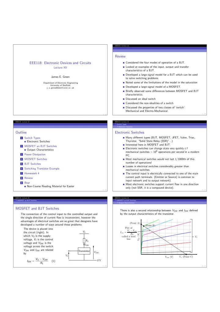
There is also a second relationship between VSW and ISW defined by the output characteristics of the transistor.
Vsw [V] Isw [A] Vi
b b b