
FOR FURTHER TECHNICAL DETAILS ON THIS PRODUCT, REQUEST CATALOG REFERENCE N340
1.128
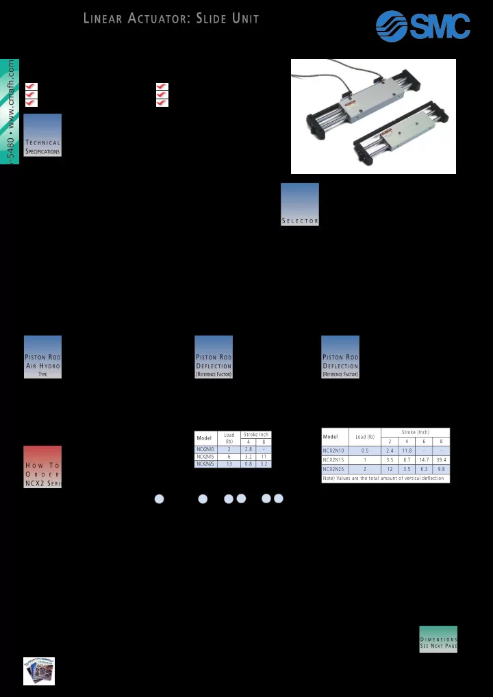
LINEAR ACTUATOR: SLIDE UNIT
SERIES NCX2
Bore sizes 10,15,25mm Slide bearing construction High accuracy positioning Magnetic sensing standard Mounting hole for shock absorber End plate housing mounting option
S E L E C T O R
Either the housing or the plate can be fixed depending upon the application. Note: on the B type mounting (see “How to Order”), the air supply is connected to the housing which is static. On the P type mounting, the air supply is connected to either end plate with the opposite end plugged. For a concentrated load at the center of the housing.
P I S T O N R O D D E F L E C T I O N
(REFERENCE FACTOR) For a concentrated load at the center of the end plate.
P I S T O N R O D D E F L E C T I O N
(REFERENCE FACTOR)
T E C H N I C A L SPECIFICATIONS
Note 1) please position the center of gravity of the load and the slide unit as close as possible. If this is not possible, please contact a SMCRepresentative.
Stroke (Inch) Model Load (lb) 2 4 6 8 NCX2N10 0.5 2.4 11.8
- NCX2N15
1 3.5 8.7 14.7 39.4 NCX2N25 2 12 3.5 6.3 9.8 Note) Values are the total amount of vertical deflection D I M E N S I O N S S E E N E X T P A G E ☞ Model Load (lb) Stroke Inch 4 NCX2N10 2 2.8
- NCX2N15
6 3.2 11 NCX2N25 13 0.8 3.2 8
H O W T O O
R D E R
NCX2 S E R I E S S L I D E U N I T
NC D X 2 N
B ……Housing fixed P ……End plate fixed 10, 15, 25
B O R E ( M M) S T R O K E ( I N C H) M O U N T I N G
SLIDE UNIT SERIES NCX2
Type Fluid Proof Pressure Max Operating Pressure Min Operating Pressure Ambient and Operating Fluid Temp Piston Speed (Non-Lube Type) Cushion Stroke Adjustment Range Note 1) Max Movable Load Non Rotating Accuracy (Except for bending of Piston Rod) NCX2N10 NCX2N1S NCX2N2S NCX2N10 NCX2N1S NCX2N2S NCX2N10 NCX2N1S NCX2N2S Non-Lube Type / Air-Hydro Type Air / LP Oil 1.5MPa / 220 PSI 1MPa / 150 PSI 0.15MPa / 22 PSI 0.15MPa / 22 PSI 0.1MPa / 15 PSI 5 ~ 60ºC / 40 ~ 140OF See List Below With Shock Absorber (Option) 2~25.4mm / +0.08 ~ -1 inch 1Kg / 2.2 lb 3Kg / 6.6 lb 6Kg / 13.2 lb +0.1O +0.04O +0.02O
S T R O K E A D J U S T M E N T A U T O S W I T C H N O O F A U T O S W I T C H E S P I S T O N R O D A I R H Y D R O
TYPE Model NCX2H15 NCX2H25 End Plate Mounted * 0.2 ~ 1.6in/sec Housing Mounted 0.2 ~ 2in/sec 0.2 ~ 4in/sec
- ……Without Auto Switch
D ……With Auto Switch
A U T OS W I T C H C A P A B L E
N ...Non-Lube H ...Air Hydro Type (except ø10)
T Y P E
100 … 1 200 … 2 300 … 3 400 … 4 500 … 5 600 … 6 700 … 7 800 … 8
- ……With Adjustment Bolts (Std)
B ……With Shock Absorber BC …With Cap Type Shock Absorber BCS …With One Cap Type Shock Absorber
- ……2 Pieces
S ……1 Piece See Accessories Deflection x 10-3 inch
Courtesy of CMA/Flodyne/Hydradyne ▪ Motion Control ▪ Hydraulic ▪ Pneumatic ▪ Electrical ▪ Mechanical ▪ (800) 426-5480 ▪ www.cmafh.com