SAR Phenomenology Dr. Armin Doerry Detailed contact information at - - PDF document

sar phenomenology
SMART_READER_LITE
LIVE PREVIEW

SAR Phenomenology Dr. Armin Doerry Detailed contact information at - - PDF document

10/12/2017 SAR Phenomenology Dr. Armin Doerry Detailed contact information at www.doerry.us This presentation is an informal communication intended for a limited audience comprised of attendees to the Institute for Computational and


slide-1
SLIDE 1

10/12/2017 1

SAR Phenomenology

  • Dr. Armin Doerry

Detailed contact information at www.doerry.us

1

This presentation is an informal communication intended for a limited audience comprised

  • f attendees to the Institute for Computational and Experimental Research in Mathematics

(ICERM) Semester Program on "Mathematical and Computational Challenges in Radar and Seismic Reconstruction“ (September 6 ‐ December 8, 2017). This presentation is not intended for further distribution, dissemination, or publication, either whole or in part.
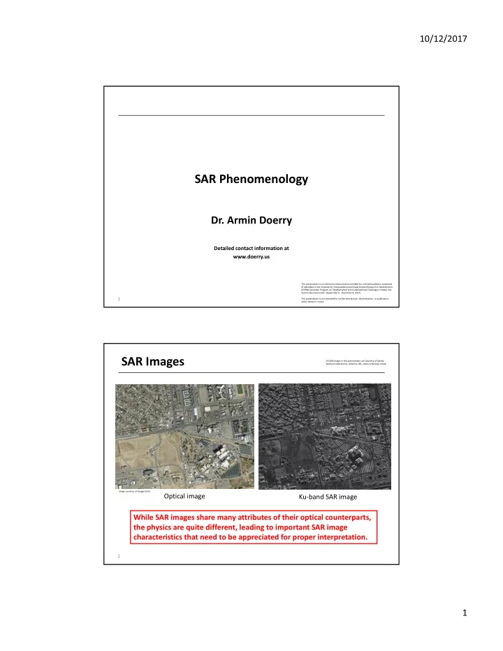
SAR Images

2

While SAR images share many attributes of their optical counterparts, the physics are quite different, leading to important SAR image characteristics that need to be appreciated for proper interpretation.

Ku‐band SAR image Optical image

Image courtesy of Google Earth All SAR images in this presentation are Courtesy of Sandia National Laboratories, Airborne ISR, unless otherwise noted.

slide-2
SLIDE 2

10/12/2017 2

Image Basics – Pixel Spacing

Pixel

– Pixels are “picture elements” that make up an image. – their ‘spacing’ is not necessarily the image resolution.

  • the ratio of resolution to pixel spacing is the ‘oversampling factor’

– We generally desire pixel spacing to be finer than the resolution – typically 1.18 to 1.5 for many SAR systems. same resolution, but coarser pixel spacing

1.0 m resolution 0.3 m resolution 0.1 m resolution

Image Basics – Resolution

4

Finer resolution clearly

  • ffers more detail – but at

the expense of greater latency and more complicated processing

slide-3
SLIDE 3

10/12/2017 3

Geometric Distortions ‐ Layover

5

Cone of constant Doppler

* *

Ground plane Sphere of constant range

The intersection of constant range and constant Doppler manifests as a circle. All locations on the circle have same range and Doppler. This circle intersects the ground at as many as two locations. The real antenna beam selects which of these makes it into the data. However, any target above

  • r below the ground on the circle and in the beam will map to the ground intersection point. This

is called “layover.”

Geometric Distortions – Layover

6

constant range contour Since the SAR renders range, tops of tall

  • bjects are nearer to the radar than their

bottoms, so appear at nearer ranges in the SAR image. They ‘lean forward’ towards the radar, projecting to nearer ranges. This is the opposite of optical images, which causes tops of tall objects to lean away, projecting to farther ranges on the ground.

Far range Near range

slide-4
SLIDE 4

10/12/2017 4

Geometric Distortions – Layover

7 Far range Near range

By rotating the image so that near range is at the top of the image, the image looks more natural. This is more a matter of personal preference.

ground plane

Geometric Distortions – Layover

8

Layover is in the direction towards the closest approach of the flight path. Shadows are always away from the radar. Consequently shadows are not always

  • pposite the layover direction.

Layover is in the direction towards the closest approach of the flight path. Shadows are always away from the radar. Consequently shadows are not always

  • pposite the layover direction.

Shadow Layover

slide-5
SLIDE 5

10/12/2017 5

Geometric Distortions

9

Slant plane Ground plane The “Ground plane” is a locally level plane at the SRP. The “Slant Plane” customarily refers to the plane defined by the radar’s straight‐line flight path and the SRP.

SRP

Literature often refers to “Slant‐plane images” versus “Ground‐plane images.” In both cases the image is still of the ground, and focused to the ground. The distinction often refers to pixelation of the image, and whether it is in equal increments of slant range, or equal increments of ground‐range. Layover is, of course, unaffected.

Geometric Distortions – Range‐Doppler Grid

10

Constant‐range spheres intersect the ground as circles, and constant‐Doppler cones intersect the ground as hyperbolas. Consequently, a range‐Doppler grid is ‘warped’ with respect to a Cartesian grid

  • n the ground.

This manifests most evident with ‘wide‐ angle’ SAR images, especially at finer resolutions and nearer ranges. For small areas significantly far away in a broadside direction, the local range‐Doppler grid is approximately square.

  • 10
  • 5

5 10

  • 10
  • 8
  • 6
  • 4
  • 2

2 4 6 8 10 x y

slide-6
SLIDE 6

10/12/2017 6

Imaging Geometry

slant range vs. ground range

– consider two targets that are not too far apart in range – difference in slant range will be less than difference in ground range

  • related by the cosine of the

local grazing angle cos

r y g

    grazing angle (nearly same for both targets) cos

g

 

– also true for resolution

cos

r y g

   

  • most accurate if using the actual depression

angle to the target

  • using nominal depression angle at SRP often

a good approximation

11

Imaging Geometry

The actual grazing angle changes slightly over the imaged swath.

  • shallower at farther ranges,
  • steeper at nearer ranges.

– more noticeable as swath width becomes an increasing fraction

  • f the slant range.

12

slide-7
SLIDE 7

10/12/2017 7

Imaging Geometry

Equal ground spacing does not appear as equal slant‐ range spacing.

– appear farther apart at far ranges, – appear closer together at near ranges.

ground truth SAR image with equal slant‐range spacing effect is in range only, not azimuth This is the native output for range‐Doppler image formation algorithms like the Polar Format Algorithm (PFA). Of course images can always be resampled to

  • ther grids.

This is not an issue for tomographic algorithms like Backprojection

13 (other effects in azimuth)

Geometric Distortions – Range‐Doppler Grid

14

UHF Note “curve” in roads

slide-8
SLIDE 8

10/12/2017 8

Canonical Reflectors

15

Canonical reflectors are those for which the RCS is simple and can be calculated in closed‐form solution. They are generally intended to approximate a singular point reflector which is particularly useful for evaluating the ‘goodness’ of SAR images.

Canonical Reflectors

16

Canonical reflector arrays are often used as SAR system test sites, to gauge performance of the SAR system during flight.

slide-9
SLIDE 9

10/12/2017 9

Target Scattering

– A sphere (e.g. domed/rounded surfaces)

  • isotropic

– looks the same from any direction

  • RCS depends on radii of curvature
  • looks like a point target
  • r a blob

– Cylinder (e.g. pipelines, utility wires, structural edges, fences)

  • single‐axis isotropic

– RCS peak broadside to cylinder

  • RCS proportional to diameter
  • looks like a line

17

weak strong

Target Scattering

– Flat Plate (e.g. lake, roads, runways, paved areas)

  • not isotropic at all

– narrow RCS peak when normal to surface – like a mirror

  • looks like a point or blob at normal incidence
  • looks dark at non‐normal incidence

– Dihedrals (e.g. buildings, stationary vehicles)

  • nearly single‐axis isotropic

– within inside envelope – RCS peak normal to dihedral joining edge

  • RCS proportional to plate sizes
  • looks like a line

– located at joining edge strong weak

18

slide-10
SLIDE 10

10/12/2017 10

Target Scattering

– Top Hat (e.g. utility poles, tree trunks, vent pipes)

  • nearly isotropic
  • RCS depends on dimensions
  • looks like a point target
  • r blob

– Trihedrals (corner reflectors) (e.g. building inside corners, window wells, truck beds)

  • nearly isotropic

– within inside envelope

  • RCS proportional to plate sizes
  • looks like a point or blob

– located at apex

19

Complicated Targets

20

Even just a handful of scatterers within a resolution cell will interfere with each other (adding in and out of phase) so that the RCS is a complicated and sensitive function of aspect angle. This is the basis for Swerling models; statistical models of RCS depending on nature of scatterers and whether they remain coherent from pulse‐to‐pulse, or scan‐to‐scan.

10 20 30 40 30 210 60 240 90 270 120 300 150 330 180 RCS (dBsm) scatterer position

slide-11
SLIDE 11

10/12/2017 11

Slicy

21

An interesting ‘quasi’‐standard target for a number of SAR target recognition studies is known as “Slicy”, which is made up of a special arrangement of cutouts and

  • ther canonical components.

Distributed Clutter – Speckle

22

Ku‐band The “graininess” in a SAR image is due to the distributed nature of the target area, and the fact that the waveform is coherent and relatively narrow‐band. The patch of ground that is contained in a resolution cell is in fact a complicated scatterer, with RCS that depends on the superposition of many tiny surface elements. Consequently, the RCS is generally described statistically per unit area. The “graininess” in a SAR image is due to the distributed nature of the target area, and the fact that the waveform is coherent and relatively narrow‐band. The patch of ground that is contained in a resolution cell is in fact a complicated scatterer, with RCS that depends on the superposition of many tiny surface elements. Consequently, the RCS is generally described statistically per unit area.

slide-12
SLIDE 12

10/12/2017 12

Smooth versus Rough

23

Ku‐band The “brightness” of an area generally corresponds to the roughness of its surface. The “brightness” of an area generally corresponds to the roughness of its surface.

Smooth versus Rough – Oil Spills

24

Oil slicks dampen the wind‐ driven capillary waves, and manifest as dark regions on the sea surface. Oil slicks dampen the wind‐ driven capillary waves, and manifest as dark regions on the sea surface. Natural oil seeps off the coast

  • f Santa Barbara, CA

Ku‐band

slide-13
SLIDE 13

10/12/2017 13

Frequency Dependence

25

Roughness is measured against

  • wavelength. Rough at one wavelength

may be smooth at another. Roughness is measured against

  • wavelength. Rough at one wavelength

may be smooth at another.

Polarization Dependence

26

Targets are often also sensitive to polarization of the incident radiation., and re‐radiate preferred polarizations. Some features “light up” with some polarization combinations, and others “light up” with other polarization combinations. Sometimes, target features we want to suppress can be made to “go dark” with certain polarization combinations. H H H V V H V V X‐band

slide-14
SLIDE 14

10/12/2017 14

Polarization Dependence

27

Different polarizations, or perhaps functions of polarizations, are often displayed with different colors. Different polarizations, or perhaps functions of polarizations, are often displayed with different colors.

Polarization Canonical Targets

28

22.5 deg. 45 deg.

Incident polarization Reflected polarization Incident polarization Reflected polarization Incident polarization Reflected polarization

For polarimetric calibration, a popular target is the

  • dihedral. With a boresight orientation, it will rotate

polarization by twice the target rotation angle. Polarization rotation depends on the nature

  • f the bounce(s).
slide-15
SLIDE 15

10/12/2017 15

Stealth Targets

29

Ku‐band When a target either absorbs of redirects its reflected energy away from the receiver, it exhibits “Stealth.” While this can be relatively easy at times, and is not uncommon either by design or by accident, it is far harder to cover up a shadow. Ku‐band

Shadows

30

Some objects are more readily identified by their shadows. This is also true for otherwise stealthy targets. Ka‐band

slide-16
SLIDE 16

10/12/2017 16

Shadow – 3D Shape Reconstruction

31

The radar provides not only its own shadow, but can render the shadow in the SAR image. Collecting shadows from enough different aspects allows reconstruction of the shape of the 3D target. The radar provides not only its own shadow, but can render the shadow in the SAR image. Collecting shadows from enough different aspects allows reconstruction of the shape of the 3D target.

Multipath Effects

32

The normal assumption for radar is the “Born approximation,” which says essentially that the only field that scatters is the incident field. That is, the SAR image is normally assumed to be only direct scattering from an image location. Real‐life isn’t quite so pretty. “Multipath” is the phenomenon that a field may be reflected more than once before echoing back to the SAR receiver. Energy delayed in this manner maps to locations farther in range than the scattering object. Multipath can happen in the target scene, or can even happen at the aircraft.

slide-17
SLIDE 17

10/12/2017 17

Multipath Effects

33

Jet engine inlets often exhibit characteristic multipath effects. Ku‐band

Far range Near range

Ku‐band

Side of monument Ground

Ray trace

Multipath Effects – Ground Bounce

34

Direct return, Single bounce Double bounce Triple bounce This image of a tank seems to suggest 3 cannon barrels. However careful analysis shows that along with the direct return, we have multipath effects of double and triple bounces involving the ground.

slide-18
SLIDE 18

10/12/2017 18

Multipath Effects

35

This electrical substation has a number of discrete but highly reflective features that allow substantial multipath opportunities. Images of such targets often look cluttered, with energy bleeding into shadows.

Penetration – Weather

36

Microwave radiation is well known to be able to penetrate clouds, fog, rain, snow, sandstorms, dust, and smoke. This is due to its longer wavelengths than optical or even IR systems.

This image was formed at night through an overcast with occasional light rain.

slide-19
SLIDE 19

10/12/2017 19

Penetration – Structures

37

Ka‐band In this SAR image, we easily penetrate the fabric tents to see the equipment that is hidden from optical view.

Penetration

38

Foliage Penetration (FOPEN) Generally VHF/UHF frequencies can be used to penetrate foliage. A problem is that at these longer wavelengths, we are generally limited in bandwidth, thereby limiting resolution. Furthermore, these frequencies are popular with

  • ther users, and interference can be

a problem. Shorter wavelengths in the microwave region can sometimes penetrate relatively sparse foliage. This is sometimes attributed to “peek‐through,” although the transmission path may not be quite so clean, exhibiting multipath effects. Ground Penetration (GPEN) Ground penetration is mainly a function of soil moisture. Even L‐ band (1‐2 GHz) has been shown to penetrate dry sand to several

  • meters. A problem for airborne SAR

is that below‐ground targets with significant attenuation must typically compete with surface clutter. Seawater Penetration While microwave frequencies cannot meaningfully penetrate seawater, it has been shown that submerged

  • bjects do in fact influence sea‐surface

characteristics that often can indeed be detected.

slide-20
SLIDE 20

10/12/2017 20

Atmosphere Issues

39

The assumption that the atmosphere is “free space” or even “homogeneous” ignores refraction due to gradients in the atmosphere, primarily humidity

  • gradients. This can interfere with high‐

fidelity image formation. The assumption that the atmosphere is “free space” or even “homogeneous” ignores refraction due to gradients in the atmosphere, primarily humidity

  • gradients. This can interfere with high‐

fidelity image formation.

Spatially‐variant defocus Spatially‐variant illumination (travelling hill phenomenon)

Moving Features – Translation

40

Vehicle stopped at gate As vehicle begins to move, its Doppler signature begins to shift and smear As vehicle begins to move faster , its Doppler signature continues to shift and smear more Vehicle shadow begins to move Vehicle shadow continues to move Vehicle shadow behind direct return

A line‐of‐sight velocity causes a shift in Doppler of the direct

  • return. A cross‐range velocity

causes a smearing of Doppler. A line‐of‐sight velocity causes a shift in Doppler of the direct

  • return. A cross‐range velocity

causes a smearing of Doppler.

Ku‐band

slide-21
SLIDE 21

10/12/2017 21

Moving Features – Translation

41

Slow‐Moving Train Train Tracks

Moving Features – Vibration & Rotation

42

Vibration and rotation involve alternating positive and negative line‐of‐sight velocities during a synthetic aperture. These will tend to throw Doppler sidelobes in both directions. Vibration and rotation involve alternating positive and negative line‐of‐sight velocities during a synthetic aperture. These will tend to throw Doppler sidelobes in both directions.

Corner reflector on vibration apparatus

Image courtesy of University of New Mexico

Truck with engine running SAR image Clutter cancelled

slide-22
SLIDE 22

10/12/2017 22

Moving Features

43

Vibrating vent Wind turbines Rotating antenna

Image Courtesy of General Atomics, ASI.

The motion information is in the sidelobes. The motion information is in the sidelobes.

Moving Features – Blowing Trees

44

Foliage movement is particularly sensitive to wind. Foliage movement is particularly sensitive to wind.

slide-23
SLIDE 23

10/12/2017 23

Moving Features – People

45

Golfer direct return Golfer shadow Golfer shadow People generally can’t hold still enough to focus

  • well. They tend to smear

in Doppler even when standing still. However, their shadows don’t exhibit Doppler effects. Golf putting green Ka‐band Golf bag Person Ku‐band

Coherence Between Images

46

SAR assumes a stationary target scene. Two SAR images of the same identical scene, taken from the same geometry, but at different times, will be identical in all respects except for uncorrelated noise. A coherence map should show high coherence except for areas of change between the imaging times, and where noise dominates. SAR assumes a stationary target scene. Two SAR images of the same identical scene, taken from the same geometry, but at different times, will be identical in all respects except for uncorrelated noise. A coherence map should show high coherence except for areas of change between the imaging times, and where noise dominates. SAR Image 1 SAR Image 2 Coherence between images Ku‐band

slide-24
SLIDE 24

10/12/2017 24

Section Summary

  • SAR images contain many features that correspond

to the visual world

  • There are substantial differences between SAR

images and EO/IR images

– Range‐Doppler image geometry – Much longer wavelengths

  • Can penetrate when shorter wavelengths can’t

– Requires stationary scene content to focus

  • SAR images also vary considerably from one radar

band to the next

  • SAR image pixels also feature phase information
  • Shadows might be exploited

47

Select References

  • Reflectors for SAR Performance Testing – second edition

– Sandia National Laboratories Report SAND2014‐0882

  • Radar Cross Section of Triangular Trihedral Reflector with Extended Bottom Plate

– Sandia National Laboratories Report SAND2009‐2993

  • Handbook of Radar Scattering Statistics for Terrain

– Ulaby & Dobson, ISBN 0890063362

  • Radar Reflectivity of Land and Sea

– Long, ISBN 1580531539

  • Doppler Characteristics of Sea Clutter

– Sandia National Laboratories Report SAND2010‐3828

  • Radar cross section statistics of cultural clutter at Ku‐band

  • Proc. of SPIE, Vol. 8361
  • Recovering shape from shadows in synthetic aperture radar imagery

  • Proc. of SPIE, Vol. 6947
  • Degrading effects of the lower atmosphere on long‐range airborne synthetic

aperture radar imaging

– IET Radar Sonar Navig., 2007

  • Synthetic aperture radar for disaster monitoring

  • Proc. of SPIE, Vol. 8021
  • Radar Range Measurements in the Atmosphere

– Sandia National Laboratories Report SAND2013‐1096

48