T HE Muon Ionization Cooling Experiment, to be operated at the - - PDF document

t
SMART_READER_LITE
LIVE PREVIEW

T HE Muon Ionization Cooling Experiment, to be operated at the - - PDF document

3HP2-9 1 The Cooling and Safety Design of a Pair of Binary Leads for the MICE Coupling Magnets L. Wang, S. Sun, Y. Cao, L. X. Yin, X. L. Guo, H. Pan, M. A. Green, Senior Member, IEEE, D. R. Li, A. Demello, and S. P. Virostek safety contingency,


slide-1
SLIDE 1

3HP2-9 1

The Cooling and Safety Design of a Pair of Binary Leads for the MICE Coupling Magnets

  • L. Wang, S. Sun, Y. Cao, L. X. Yin, X. L. Guo, H. Pan, M. A. Green, Senior Member, IEEE, D. R. Li, A.

Demello, and S. P. Virostek

Abstract—The key to being able to operate the superconducting solenoids in the Muon Ionization Cooling Experiment (MICE) using cryocoolers running at around 4.2 K is the application of high temperature superconducting (HTS) leads. Because the MICE magnets are not shielded, all of them will have a stray magnetic field in the region where the coolers and the HTS leads are located. The behavior of the HTS leads depends strongly on the HTS material used for the leads, the magnetic field and their warm end temperature. A pair of binary leads consisting of copper leads and HTS leads made from oriented multiple strands

  • f BSCCO wires will be used for electrical transfer of the MICE

coupling magnet for the purpose of reducing the heat leak through the leads to 4.2 K region. This paper mainly discusses the detailed design of the HTS leads and their cooling. Protection for the HTS leads during a power failure is discussed as well. Index Terms—Cu leads, HTS leads, and safety design.

  • I. INTRODUCTION

HE Muon Ionization Cooling Experiment, to be operated at the Rutherford Appleton Laboratory in UK, will provide the first demonstration of the muon ionization cooling technique, which is critical to the success of a future muon-based accelerator and neutrino factory [1]. A pair of superconducting coupling magnets will be used for the MICE cooling channel in order to keep the beam from expanding beyond the edge of the RF cavity thin windows, through which the muon beam passes [2]. The magnet is a single solenoid coil with an inner diameter of 1.5 m and a length of 281 mm, which is designed to be cooled by cryocoolers [3]. It will be powered by using a unipolar 300 A/0-20 V power supply and its maximum operation current is 210 A while the MICE cooling channel runs at gradient mode [1]. In order to reduce the heat leak induced directly from room temperature to 4.2 K, a pair of binary current leads composed

  • f conventional copper leads and high temperature

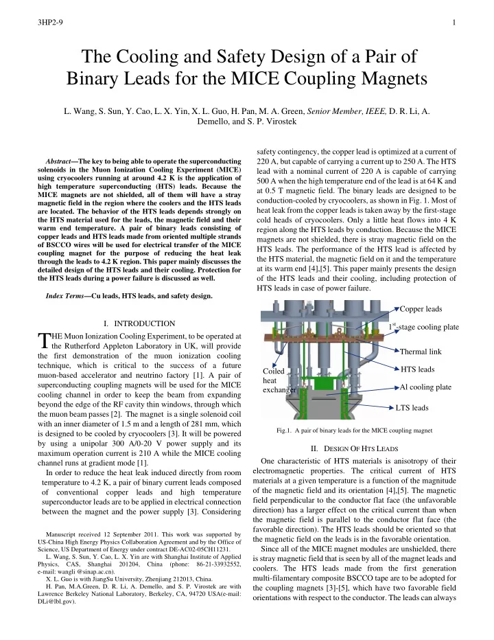
superconductor leads are to be applied in electrical connection between the magnet and the power supply [3]. Considering safety contingency, the copper lead is optimized at a current of 220 A, but capable of carrying a current up to 250 A. The HTS lead with a nominal current of 220 A is capable of carrying 500 A when the high temperature end of the lead is at 64 K and at 0.5 T magnetic field. The binary leads are designed to be conduction-cooled by cryocoolers, as shown in Fig. 1. Most of heat leak from the copper leads is taken away by the first-stage cold heads of cryocoolers. Only a little heat flows into 4 K region along the HTS leads by conduction. Because the MICE magnets are not shielded, there is stray magnetic field on the HTS leads. The performance of the HTS lead is affected by the HTS material, the magnetic field on it and the temperature at its warm end [4],[5]. This paper mainly presents the design

  • f the HTS leads and their cooling, including protection of

HTS leads in case of power failure.

c.cn). Manuscript received 12 September 2011. This work was supported by US-China High Energy Physics Collaboration Agreement and by the Office of Science, US Department of Energy under contract DE-AC02-05CH11231.

  • L. Wang, S. Sun, Y. Cao, L. X. Yin are with Shanghai Institute of Applied

Physics, CAS, Shanghai 201204, China (phone: 86-21-33932552, e-mail: wangli @sinap.a

  • X. L. Guo is with JiangSu University, Zhenjiang 212013, China.
  • H. Pan, M.A.Green, D. R. Li, A. Demello, and S. P. Virostek are with

Lawrence Berkeley National Laboratory, Berkeley, CA, 94720 USA(e-mail: DLi@lbl.gov).

Copper leads 1st-stage cooling plate

Fig.1. A pair of binary leads for the MICE coupling magnet

  • II. DESIGN OF HTS LEADS

One characteristic of HTS materials is anisotropy of their electromagnetic properties. The critical current of HTS materials at a given temperature is a function of the magnitude

  • f the magnetic field and its orientation [4],[5]. The magnetic

field perpendicular to the conductor flat face (the unfavorable direction) has a larger effect on the critical current than when the magnetic field is parallel to the conductor flat face (the favorable direction). The HTS leads should be oriented so that the magnetic field on the leads is in the favorable orientation. Since all of the MICE magnet modules are unshielded, there is stray magnetic field that is seen by all of the magnet leads and

  • coolers. The HTS leads made from the first generation

multi-filamentary composite BSCCO tape are to be adopted for the coupling magnets [3]-[5], which have two favorable field

  • rientations with respect to the conductor. The leads can always

T

Thermal link HTS leads Coiled heat exchanger Al cooling plate LTS leads

slide-2
SLIDE 2

3HP2-9 2 be oriented in favorable directions with respect to the stray field. Since the critical current of the HTS conductor is also affected by the conductor temperature, the effect of the magnetic field is usually worst at the high temperature ends of the leads. Therefore, the position and orientation of the HTS leads with respect to the coupling coil cold mass as well as their cooling are crucial.

  • A. Behavior of HTS Leads in the Magnetic Field

A cross-section of the BSCCO tape used in a typical HTS lead is shown in Fig. 2, as well as illustration of the parallel and perpendicular field directions (favorable and unfavorable directions) for the lead. Fig. 3 shows the performance factors of a commercial oriented BSCCO lead as a function of magnetic induction and temperature in parallel and perpendicular directions.

  • Fig. 2. Examples of favorable field orientation (parallel to the conductor flat

face) and unfavorable field orientations (perpendicular to the conductor flat face) for leads made from oriented HTS conductor. The lead end fins indicate the conductor flat face direction. Fig.3. The performance factors of an oriented BSCCO lead as a function of magnetic induction and temperature in parallel and perpendicular directions.

In Fig. 3, the scaling factor of 1 means that the current carried by the lead is the same as the design current carried at 64 K and zero-field on the lead. And a performance factor of 0.5 means that the lead will carry half of its design current. From Fig. 3, it is clear that the lower is the lead temperature, the higher is the lead current, and the lower is the magnet field on the lead, the higher is the lead current. The lead in an unfavorable magnetic field carries much less current than that in a favorable field. At a parallel field of 0.4 T, the lead scaling factor is about 1.4 at 50 K, 0.8 at 64 K and 0.5 at 70 K, corresponding to carrying a current of 308 A, 176 A and 110 A assuming the design current is 220 A, and of 700 A, 400 A and 250 A assuming the design current is 500 A. Therefore, in order to make the HTS leads in a magnetic field

  • perate with higher performance, first, they should be

positioned in a field as low as possible. Second, they should be

  • riented so that the external field is always going in favorable
  • directions. Finally, the temperature of the leads should be kept

as low as possible, particularly at warm end. In addition, shielding the HTS leads is a possible option as long as space is available.

  • B. Magnetic Field on HTS Leads of Coupling Magnet

In order to place the HTS leads properly in the MICE coupling magnet for better behavior, the magnetic field generated by the MICE magnets and the self-field of the leads were calculated. The position of the HTS leads with respect to the coil cold mass is determined by the magnetic field at the upper end of the HTS leads.

  • Fig. 4 shows the calculated field at worst operation case

when the MICE channel runs at a momentum of 240 MeV/c in the flip mode [3],[6]. Limited by the available space for the coupling magnet in the MICE cooling channel and considering the connection with the cooling coolers, the HTS leads are positioned at R=1.45 m away from the coil center so that the peak field at upper end of the HTS leads is less than 0.4 T, about 0.32 T. The lower end of the leads at 4 to 5 K is at about R=1.2 m away from the coil center in a field of about 0.76 T. The coordinate origin is set at the coil center point, Z means the axial direction, and R means the radial direction. The field on the leads in the coil radial direction is less than that in the axial

  • direction. At the lead upper end, Br is 0.11 T and Bz is 0.32 T in

the MICE channel. The self-field from current flowing in the lead will have a component that flows in a direction perpendicular to the flat face of the lead. Self-field may be a problem with high current

  • leads. The self-field magnetic induction Bs produced by a

current lead of radius R carrying a current I can be calculated using the following expression [5]: R I Bs ⋅ = π μ 2 (1) where µ0 is the permeability of air, µ0=4π x 10-7 Hm-1. The expression above applies whether the lead has a uniform current density or the current clustered on the outer surface of the lead. A 220 A HTS lead with an average conductor radius of 2 mm would have a self-field induction of about 0.022 T. Thus, the effect of the lead self-field is negligible.

slide-3
SLIDE 3

3HP2-9 3

1.5 2 3 3 4 5 2.5 0.6 0.5 0.4 0.3 . 1 5 0.7 0.2 0.18 0.8 0.22 0.22 0.22 0.25 0.13

Z (m) R (m)

  • 1
  • 0.5

0.5 1 0.5 1 1.5 2 Cooler Motor HTS Diode Coil I=210.1A 240MeV, Flip Mode

  • Fig. 4. Magnetic field around coupling coil in the MICE channel
  • C. HTS Leads for the Coupling Magnet

According to the above analyses, one kind of commercial leads made by HTS-110 Ltd., New Zealand is most likely candidate of HTS leads for the coupling coil [3]-[5]. The leads made by HTS-110 are suited for use in a magnetic field. The standard HTS-110 conductor is a composite that places the multi-filamentary BSCCO conductor in a low thermal conductivity Ag-Au matrix, which is put inside the G-10 tube to display tolerance for strain and thermal cycling. The HTS-110 leads have two favorable and one unfavorable direction as shown in Fig. 2. Because the upper end of the leads will be at a field of 0.32 T, from Fig. 3, in order to have additional margin, the 500 A leads at 64 K will be used for the coupling magnet. The disadvantage of using larger leads is that the heat leak into the second stage of cooler is increased. The heat leak down the leads with the upper end temperature at 64 K is 90 mW for a pair of standard 250 A leads and 130 mW for a pair of standard 500 A leads. Table 1 lists dimensions and parameters of the 500 A lead. In general, the HTS-110 leads can go above 90 K before sudden thermal runaway occurs [7]. TABLE 1 PARAMETERS of a STANDARD 500A HTS-110 LEAD

Lead Body Diameter (mm) 14.30 Nickle-plated Copper Joint Thickness (mm) 6.35 Overall Length (mm) 305 Active Lead Length (mm) ~210 Operating temp. at warm end (K) 64 Operating Current at 64K (A) 500 Conductive Heat Leak at 64K~4.2K per pair (mW) 130

The position of the HTS leads in the coupling magnet is shown in Fig. 4. And the leads should be oriented as shown in Fig.1, so that the flat face of the lead conductor is in the R-Z coordinate plane. This means that the leads leaving the 4 K region of a solenoid should be on a radial line, and the flat face

  • f the conductor should be oriented in the Z direction.
  • III. COOLING FOR CURRENT LEADS

The cooling design for current leads in the coupling magnet is as shown in Fig. 1. The cold ends of copper leads and the warm ends of HTS leads are to be cooled by the first-stage cold heads of cryo-coolers by conduction through thermal links among them. The heat coming down the copper leads from room temperature is to be intercepted by the first-stage cold heads of coolers. In order to keep the HTS lead warm end at low temperature, the temperature drop between the HTS lead warm end and the cooler first-stage cold head must be minimized. The heat transfers between copper leads and coolers, and between HTS leads and coolers must be optimized [3]. The thermal link comprises a pure copper plate and electrical insulations, which is mounted to the first-stage cooling plate by brass bolts with G-10 insulation sleeves outside. The copper plate fulfills the function of both heat and electrical transfer. Two layers of 25 um kapton film or a thin G-10 sheet with epoxy are to be used for electrical insulation. The thickness of the insulation is expected to be as thin as possible. The cold end

  • f the copper lead and the warm end of the HTS lead will be

bolted and soldered to the thermal link on opposite sides to avoid the heat from the copper lead imposed on the HTS lead

  • directly. The key points for the thermal link design are to

reduce ΔT through the electrical insulation due to poor thermal conductivity of kapton or G-10 compared with copper, i.e., to enlarge its conduction area and to shorten its conduction length. The related calculation and simulation were carried out to

  • ptimize the thermal link structure. The optimized structure

parameters are given in Fig. 5, and the simulated temperature distribution is presented in Fig. 6. Assuming the cooler first-stage cold head temperature is at 60 K and all the surfaces are in good contact, the hot spot temperature of the HTS leads is about 63.5 K, and that of the copper leads is about 67.4 K.

155 40 40 35 85 10

Fig 5. Thermal link for cooling the warm end of HTS lead

  • Fig. 6. Temperature distribution in thermal link

60K 67.4K 63.5K

slide-4
SLIDE 4

3HP2-9 4 The cold end of HTS leads is flexibly connected to niobium titanium pigtail leads from the coupling coil. It is kept cold by using flexible copper strips, which are attached to an aluminum

  • plate. The Al plate is welded onto the top helium reservoir of

the coil cold mass to transfer the cooling to the cold end of the HTS leads.

  • IV. PROTECTION OF CURRENT LEADS

Lead overheating during a fault is an important consideration for the coupling magnet design. Some failure modes such as a power failure that will cause the cooler to shut off or the malfunction of the cooler can bring about the leads to overheat and even burn out if the current can not be removed from the leads rapidly. The voltage drop along the length of the HTS leads is to be measured during normal operation. If the voltage drop along one or both magnet leads is too high for some reason, it may finally lead to the magnet quench to protect the leads from burning out. However, once the magnet quenches, the time to recover is quite long because: 1) The cold mass of about 2 tons of the coupling coil will take long time to be cooled down again after quench, and 2) The magnet charge time constant for the coupling coil is relative long of about 4 hrs. To provide the extra cooling for the leads particularly at warm end of the HTS leads is one way to prevent the HTS leads from going normal and running away while taking action such as rapidly discharging the magnet once cooler failure occurs. For the coupling magnet, considering limited space inside the cryostat, the following two ways were studied for leads’ protection cooling [3],[9].

  • A. Heat Sink

Having enough solid thermal mass with large heat capacity (e.g., extra copper in the shields) to keep in contact with the leads may be used to prevent them from getting too hot while rapidly discharging the magnet once the cooler fails. The fast discharge of the magnet will not cause the magnet to quench, as long as there is liquid helium around the coil. The calculated amount of extra metals necessary for keeping the HTS lead warm end no higher than 70 K during a rapid discharge process is about 155 kg for copper as shown in Table 2. For the current coupling magnet design, the total mass of neck shields and the first-stage cold head cooling plates is around 120 kg, which are made of copper and directly connected with the leads.

  • B. Heat Exchanger

Using sensible heat of boil off helium from the magnet to cool the HTS leads during a rapid discharge is another possible way to protect the leads from thermal runaway. During the rapid discharge process, about 11 liters of liquid helium around the magnet will boil off due to AC losses and static heat load at 4.2K. The boiled off helium at averaged mass flow rate of 0.257 g/s will flow though a coiled heat exchanger attached to the first-stage cold heads of the coolers to keep both the shields and the HTS leads cold, as shown in Fig. 1. The heat exchanger is designed to be made of copper tubing of 8 mm in inner diameter and 3~4 meter in length. The pressure drop along it is about 300Pa. TABLE 2 AMOUNT of METALS NEEDED to KEEP the WARM END of the HTS LEADS COLD DURING a FAST DISCHARGE.

Time for a rapid discharge (s) 5400 Average rapid discharge AC loss (W) 2.95 Static heat load to cold mass at 4.2 K (W) 2.2 Static heat load to cold mass at 60 K (W) 54 Temperature of Cu with cooler cooling (K) 55 Temperature of Cu w/o cooler cooling (K) 60

  • Max. temperature of HTS leads during discharge (K)

<70 Heat leak along cooper leads (W) 19.3 Heat form Cu leads to be absorbed during fast discharge (kJ) 104.22 Heat to be absorbed at 4.2K during fast discharge (kJ) 2.781 Cu mass needed w/o cooler cooling (kg) 154.4

  • C. Protection of the LTS Leads

Protection of the low temperature superconducting (LTS) leads is also very important, because a failure of these leads means the cold mass must be repaired [7]. The LTS leads must have a minimum propagation zone length that is greater than their length. In addition, the LTS leads must be well connected to 4 K cooling, even though the temperature margin for these leads is quite large, which is more than 2 K.

  • V. CONCLUSION

This paper presents the detailed design of HTS leads and their cooling for the MICE coupling magnet. The HTS leads made from the oriented BSCCO conductor should be placed in a magnetic field as low as possible and positioned so that the field always goes in favorable directions. The temperature at warm end of the HTS leads should be kept as low as possible. In order to protect the leads from overheating and burning out in case of power failure, combination of the heat sink using solid thermal mass and the heat exchanger utilizing the sensible heat of helium is to be used for extra cooling. REFERENCES

[1]

  • G. Gregoire, G. Ryckewaert, L. Chevalier, et al, “MICE and International

Muon Ionization Cooling Experiment Technical Reference Document”, Available: http://hep04.phys.itt.edu/cooldemo. [2]

  • D. R. Li, M. A. Green, S. P.Virostek, M. S. Zisman, “Progress on the RF

Coupling Module for the MICE Channel”, in Proc 2005 Particle Accelerator Conference, Knoxville TN, 2005, pp. 3417-3419. [3] L.Wang, “Engineering design of MICE/MUCOOL coupling solenoid magnets”, Harbin Institute of Technology, Dec. 2008. [4]

  • M. A. Green, et al, “The Effect of Magnetic Field on the Position of HTS

Leads and the Cooler in the Service Tower of the MICE Focusing Magnet”, IEEE Transactions on Applied Superconductivity ,vol. 18, No. 2, 2008, pp. 1447-1450, [5] Michael A. Green, “The Effect of Magnetic Field on HTS Leads What Happens When the Power Fails at RAL”, LBNL-62459, 2007. [6] Ying zhao Lei, Magnetic Calculation for Axisymmetric Coil, Chinese Computation Press, 1991, pp. 4~14 (in Chinese) [7]

  • M. A. Green, H. Pan, S. O. Prestemon and S. Virostek, “Protecting the

Lead of a Powered Magnet that is protected with Diodes and Resistors,” IEEE Transactions on Applied Superconductivity, vol. 22, No. 3 (this volume), 2012, submitted for publication. [8]

  • M. A. Green, H. Wu, L. Wang et al, “AC Losses in the MICE Channel

Magnets, is this a Curse or a Blessing?”, LBNL-63804, MICE Note 195, 2008, http://www.mice.iit.edu ,