Thanks Multicore Real-Time Systems Guan Nan, Martin Stigge, - - PDF document

thanks
SMART_READER_LITE
LIVE PREVIEW

Thanks Multicore Real-Time Systems Guan Nan, Martin Stigge, - - PDF document

2010-09-11 Part 2 Thanks Multicore Real-Time Systems Guan Nan, Martin Stigge, Mingsong Lv, Zhang Yi, -- Challenges & Solutions Erik Hagersten, Bengt Jonsson and Alexander Medvedev Wang Yi Uppsala University VTSA Summer School


slide-1
SLIDE 1

2010-09-11 1

Multicore Real-Time Systems

  • - Challenges & Solutions

Wang Yi Uppsala University VTSA Summer School Luxembourg, Sept 2010

Part 2

Thanks

Guan Nan, Martin Stigge, Mingsong Lv, Zhang Yi, Erik Hagersten, Bengt Jonsson and Alexander Medvedev

2

OUTLINE

 Multicore Challenges (Real-Time Applications?)

  • Why and what are multicores?
  • What we are doing in Uppsala: CoDeR-MP
  • The timing analysis problem

 Possible Solutions – Partition/Isolation

  • Dealing with Cache Contention [EMSOFT 2009]
  • Dealing with Bus Interference [RTSS 2010]
  • Dealing with Core Sharing [RTAS 2010]

3 CPU L1 CPU L1 CPU L1 CPU L1 CPU L1 CPU L1 CPU L1 CPU L1

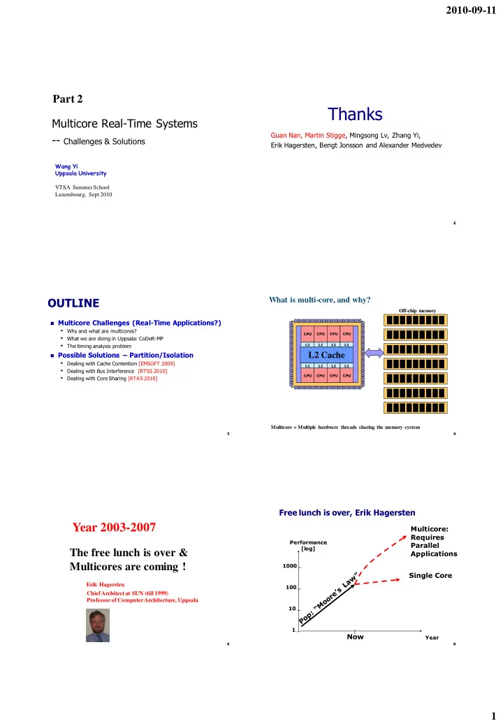
What is multi-core, and why?

L2 Cache

Off-chip memory

4

Multicore = Multiple hardware threads sharing the memory system

The free lunch is over & Multicores are coming !

Erik Hagersten Chief Architect at SUN (till 1999) Professor of Computer Architecture, Uppsala

Year 2003-2007

5

1 10 100 1000

Now

Performance [log] Year

Single Core Multicore: Requires Parallel Applications

Free lunch is over, Erik Hagersten

6

slide-2
SLIDE 2

2010-09-11 2

Theoretically you may get:

 Higher Performance

  • Increasing the cores -- unlimited computing power  !

 Lower Power Consumption

  • Increasing the cores, decreasing the frequency

 Performance (IPC) = Cores * F  2* Cores * F/2  Cores * F  Power = C * V2 * F  2* C * (V /2)2 * F/2  C * V2 /4 * F

 Keep the “same performance” using ¼ of the

energy (by doubling the cores)

7

This sounds great for embedded & real-time applications!

CPU L1 CPU L1 CPU L1 CPU L1 CPU L1 CPU L1 CPU L1 CPU L1

Shared Resources

Bandwidth Multicore Challenges

L2 Cache

Off-chip memory Real-time applications?

  • - Cache contention
  • - Bus interference
  • - Multiprocessor scheduling

Weak memory models - locking Cheap/expensive Synchronization

8

UPMARC:

Uppsala Programming Multicore Architecture Research Center

Awarded by the Swedish Research Council 10 millions US$: 2008 -- 2018

Year 2008 (June)

Similar centers: Stanford, UC Berkeley

9

UPMARC Research Areas

Applications & Algorithms

 Climate simulation  PDE solvers  Parallel algorithms for RT signal processing  Parallelization of network protocols

Verification & Language Technology

 Erlang, language constructs/libraries, run-time systems  Static analysis, Model-checking , testing, UPPAAL

Resource Management

 Efficiency: performance opt.  Predictability: real-time applications

High Performance Computing Computer Networks CPU

L1

CPU

L1

CPU

L1

CPU

L1

CPU

L1

CPU

L1

CPU

L1

CPU

L1 10 L2

CoDeR-MP:

Computationally Demanding Real-Time Applications on Multicore Platforms

Awarded by the Swedish Strategic Research Foundation 3 millions US$: 2009 -- 2014

Year 2008 (November)

11

Objective (CoDeR-MP)

New techniques for

  • High-performance software for soft RT applications &
  • Predictable software for hard RT applications
  • n multicore
  • Control Software for Industrial Robots – ABB robotics
  • Tracking with parallel particle filter – SAAB

Industry participation

slide-3
SLIDE 3

2010-09-11 3

Real-Time Tracking with parallel particle filter – SAAB

Parallelization (Speed-up for PF algorithms)

1 2 3 4 5 6 7 8 1 2 3 4 5 6 7 8 Number of cores M Speed-up Number of particles N = 10000 1 2 3 4 5 6 7 8 1 2 3 4 5 6 7 8 Number of cores M Speed-up Number of particles N = 1000 1 2 3 4 5 6 7 8 1 2 3 4 5 6 7 8 Number of cores M Speed-up Number of particles N = 500 1 2 3 4 5 6 7 8 1 2 3 4 5 6 7 8 Number of cores M Speed-up Number of particles N = 100 GDPF RNA GPF RPA Linear speed up

Real-Time Control – ABB Robotics

A B C D

Commands High-level instructions Precise moves Requests

Welding program

IRC5 robot controller

Mixed Hard and Soft Real-Time Tasks 20% hard real-time tasks Main concerns: Isolation between hard & soft tasks: “fire walls” Real-time guarantee for the 20% “super” RT tasks Migration to multicore?

OUTLINE

 Multicore Challenges

  • Why and what are multicores?
  • What we are doing in Uppsala: CoDeR-MP
  • The timing analysis problem

 Possible Solutions – Partition/Isolation

  • Dealing with Cache Contention [EMSOFT 2009]
  • Dealing with Bus Interference [RTSS 2010]
  • Dealing with Core Sharing [RTAS 2010]

16

task3

Single-Processor Timing Analysis

Sequential Case (WCET analysis) Concurrent Case (Schedulability analysis)

WCRT=WCET WCRT WCRT

Non- deterministic releases

task1 task1 task2

17

On single processor:

18

WCET = #instructions + “cache miss penalty”

“Cache miss penalty” can be estimated “precisely” by e.g abstract interpretation – based on the history of executions

slide-4
SLIDE 4

2010-09-11 4

On multicore processor:

19

WCET = #instructions + “cache miss penalty” + …

“Cache miss penalty” can be much larger due to cache contentions from the other cores … and also bus delays WCET of a single task can not be estimated in isolation

mcol cnt mcol mcol mcol sha mcol susane mcol susans 50000 100000 150000 200000 250000 300000 350000

Execution time (uS) without cache partitioning

An Experiment on a LINUX machine with 2 cores

WCET (vary 10 – 50%) mcol runs with different programs (Zhang Y i)

20

An Example Architecture

core 1 core 2 core 3 core 4

Private L1 cache Private L1 cache Private L1 cache Private L1 cache

21

Shared L2 cache

Cache analysis on multicore

 L2 cache contents of task 1 may be over-written by task 2

Task 1 Task 2 Task 3 Task 4

22

Cache analysis on multicore

 L2 cache contents of task 1 may be over-written by task 2

Task 1 Task 2 Task 3 Task 4

23

Cache analysis on multicore

Private L1 cache Private L1 cache Private L1 cache Private L1 cache

Shared L2 cache

24

Task 1 Task 2 Task 3 Task 4

slide-5
SLIDE 5

2010-09-11 5

The multicore challenge: WCET analysis

 Must explore all interleavings of “execution paths” on all cores  Must represent “precise” timing information on each core (to keep

track of the progress on each core and cache contents)

25

The multicore challenge: Schedulability analysis

 #cores < #tasks Task 1 Task 2 Task 3 Task 4 Task 5

26

Cyclic dependence

27

Multicore schedulability analysis WCET analysis

The “Impossible” Problem

1.

We must “schedule” the shared cache lines

2.

We must “schedule” the shared memory bus

  • when cache misses ocur

3.

We must “schedule” the shared cores

28

OUTLINE

 Multicore Challenges

  • Why and what are multicores?
  • What we are doing in Uppsala: CoDeR-MP
  • The timing analysis problem

 Possible Solutions – Partition/Isolation

  • Dealing with Shared Caches [EMSOFT 2009]
  • Dealing with Bus Interference [RTSS 2010]
  • Dealing with Core Sharing [RTAS 2010]

29

OUTLINE

 Multicore Challenges

  • Why and what are multicores?
  • What we are doing in Uppsala: CoDeR-MP
  • The timing analysis problem

 Possible Solutions – Partition/Isolation

  • Dealing with Shared Caches [EMSOFT 2009]
  • Dealing with Bus Interference [RTSS 2010]
  • Dealing with Core Sharing [RTAS 2010]

30

slide-6
SLIDE 6

2010-09-11 6

Cache analysis on multicore

Private L1 cache Private L1 cache Private L1 cache Private L1 cache

Shared L2 cache

31

Task 1 Task 2 Task 3 Task 4

Cache-Coloring: partitioning and isolation

Task 1 Task 2 Task 3 Task 4

32

Cache-Coloring: partitioning and isolation

Task 1 Task 2 Task 3 Task 4

33

WCET can be estimated using static techniques for single processor platforms (for the given portion L2 cache)

Cache-Coloring: partitioning and isolation

 E.g. LINUX – Power5 (16 colors)

… …

Logical Pages of Task A Logical Pages of Task B Physical Pages

… … … …

L2 Cache controlled by software (OS) indexed by hardware

34

mcol cnt mcol mcol mcol sha mcol susane mcol susans 50000 100000 150000 200000 250000 300000 350000

Execution time (uS) without cache partitioning

mcol cnt mcol mcol mcol sha mcol susane mcol susans 20000 40000 60000 80000 100000 120000 140000 160000 180000 200000 220000 240000 260000 280000 300000 320000 340000

Execution time (uS) with cache partitioning

An Experiment on a LINUX machine with 2 cores with Cache Coloring/Partitioning [ZhangYi et al]

35

What to do when #tasks > #cores ?

36

slide-7
SLIDE 7

2010-09-11 7

Task partitioning

L2

Core 1

L1

Core 2

L1 L2

Core 3

L1 L2 L2

Core 4

L1

37

Task 5 Task 6 Task 5 Task 100 Task 8 Task 7 Task 4 Task 13

What to do when #tasks > #cores ?

Cache-Aware Scheduling and Analysis for Multicores

[EMSOFT 2009]

38

Main message:

  • “Isolation”: tasks of “same color” should not run at the same time
  • The schedulability problem can be solved as an LP problem

Task Partitioning & Scheduling

 Color assignment: assign cores with “cache colors”

  • Equally or according to some policy e.g. cores devoted to

critical tasks get more colors

  • WCET analysis for tasks on different cores and colors

 Task assignment: partition tasks onto cores

  • Partition-based multiprocessor scheduling
  • Challenge: tasks may have different WECTs on different cores

 Global scheduling: need dynamic coloring (expensive

without hardware support)

39

What happens when L2 cache miss?

  • - extra delays due to bus contention

40

core 1 core 2 core 3 core 4

Private L1 cache Private L1 cache Private L1 cache Private L1 cache

Shared L2 cache Memory bus

OUTLINE

 Multicore Challenges

  • Why and what are multicores?
  • What we are doing in Uppsala: CoDeR-MP
  • The timing analysis problem

 Possible Solutions – Partition/Isolation

  • Dealing with Shared Caches [EMSOFT 2009]
  • Dealing with Bus Interference [RTSS 2010]
  • Dealing with Core Sharing [RTAS 2010]

41

Bus Intererence Estimation & WCET Analysis

42

Core 0

L1 I-Cache L1 D-Cache

Core 1

L1 I-Cache L1 D-Cache Shared Memory Bus Off-Chip Memory

Duo-core processor with private L1 cache and shared memory bus

slide-8
SLIDE 8

2010-09-11 8

Combining Abstract Interpretation and Model Checking for Multicore WCET Analysis [RTSS 2010] Basic Idea:

Construct a timed model -- describing all possible timed traces of bus requests, that are possible from each core

43

Combining Static Analysis & Model-Checking

44 L1 Cache Config. T ask 1 CFG Core 1 L1 Cache Analysis L1 CHMC L1 Cache Config. T ask 2 CFG Core 2 L1 Cache Analysis L1 CHMC Shared Bus Analysis Using MC WCET of T ask 1 WCET of T ask 2 Bus Configurations (1) Local cache analysis by abstract interpretation (2) Construct a timed automaton for each program to model the precise timing information on when to access the shared bus (3) Construct a timed automaton modeling the bus arbitration (4) Explore the TA models using UPPAAL to get the WCETs

Example (CFG with CHMC info from AI analysis)

45

AM NC AH AM FM AH AH BB0 BB5 BB1 BB2 BB3 BB4

Private Cache Analysis by AI

 MUST analysis, classify instructions that are predicted as AH  MAY analysis, classify instructions that are predicted as AM  PERSISTENCE analysis, classify instructions that are predicted as FM  Everything else as Not “Classified (NC)”

46

From CFG with CHMC to Timed Automata

 Modeling AH instructions

  • If an instruction is AH, it never access the bus, so we only model

the L1 Cache access time and the instruction execution time

47 To guarantee that the automaton will stay in location “Node1” for exactly “L1Hit+InstTime” time units

c[0]: a clock variable used for core-0 to model the elapse of time L1Hit: the delay of a L1 cache hit InstTime: the execution time of an instruction

From CFG with CHMC to Timed Automata

 Modeling AM instructions

  • An AM instruction is guaranteed to access the shared bus, so we

model bus access behavior and instruction execution

48 Modeling the execution time

  • f the AM instruction

Sending a bus request Response from the bus

slide-9
SLIDE 9

2010-09-11 9

From CFG with CHMC to Timed Automata

 Modeling FM instructions

  • For an FM instruction, one should distinguish between the first

reference and the other references

49 The upper path models the first reference to the instruction, which is a cache miss (access bus) The lower path models the other references to the instruction, which are cache hits (do not access bus)

From CFG with CHMC to Timed Automata

 Modeling NC instructions

  • So for NC instructions, we have to model both possibilities of

cache misses and cache hits, and let the model checker to explore them

50 The “cache miss” case for an NC instruction The “cache hit” case for an NC instruction

From CFG with CHMC to Timed Automata

 Optimization by grouping

  • To reduce state space by reducing the number of locations and

edges, we grouping consecutive FM or AH instructions

  • Given a sequence <FM, AH, AH, FM, AH, AH>

51 The upper path models the first time the sequence is executed The lower path models all but the first time the sequence is executed

Without grouping: 12 locations With grouping: 6 locations

(PostNode not included)

Example (CFG with CHMC info from AI analysis)

52

AM NC AH AM FM AH AH BB0 BB5 BB1 BB2 BB3 BB4

The Timed Automaton Describing “Bus Interference”

53

Modeling the Shared Bus

 Example: TDMA bus schedule

  • The bus schedule is composed of consecutive segments
  • Segments are divided into slots, where each slot is assigned to
  • ne core

54

segment 0 segment 1

……

Core 0 Core 1 Core 0 Core 1 slot 0 slot 1 slot 0 slot 1

slide-10
SLIDE 10

2010-09-11 10

Modeling the TDMA Bus

 Timed automaton for the TDMA bus

55 Slot switch W aiting for new requests Not enough time left for the request Servicing a request Check if it can service the pending request Enough time and the right slot The request cannot be serviced in the current slot

Modeling the FCFS Bus

 A work-conserving non-preemptive FCFS bus

56 Receiving a bus request Service the request the first request in the queue New requests during bus service Service complete Remove the request If no pending request, go back to “RecvReq” to wait for future requests

Putting All Together

 Now, we have

  • TA models for the programs running on all cores, describing all bus

requests annotated with timing info, that are possible from the cores

  • TA model for a given bus arbitration protocol e.g TDMA, FCFS, RR …

 WCET estimation

  • Let the UPPAAL model checker explore the network of TA models
  • The WCETs are extracted from the clock constraints within the UPPAAL

model checker 

Scalability: for TDMA, it scales very well: the analysis can be done separately for each program and the bus schedule.

57

A Tool for Multicore WCET Analysis

58

Experiments and Evaluation

 WCET Benchmark programs (Maladalen)

59

Name Description # instructions bs Binary search algorithm for an array 78 edn Finite Impulse Response (FIR) filter calculations 896 fdct Fast Discrete Cosine Transform 647 insertsort Insertion sort on a reversed array 106 jfdctint Discrete Cosine Transformation on a pixel block 691 matmult Matrix multiplication 287

Results for the TDMA Bus

 System configurations

  • Duo-core or 4-core systems
  • L1 Cache size = 2KB,
  • Cache associativity = 4
  • Cache line size = 8B
  • L1 hit latency = 1 cycle
  • Instruction execution = 1 cycle
  • Bus service time = 40 cycles
  • Two different slot sizes: 100 cycles, 200 cycles

60

slide-11
SLIDE 11

2010-09-11 11

Results for the TDMA Bus

  • The WCET of each program can be calculated

independently for the TDMA bus

  • The worst-case bus delay scenario

– A bus request arrives in the slot assigned to it, but finds that

there are only 39 cycles left, which is just not enough to serve the request

– For slot size 100, worst-case delay = 39 + 100 + 40 = 179 – For slot size 200, worst-case delay = 39 + 200 + 40 = 279

  • Improvement

– (WCETAI+WC / WCETAI+MC - 1) – Describes how much our approach can tighten compared to

assuming worst-case bus delay

61

Results for the TDMA Bus

 Results for a duo-core system with slot size 100

62

Programs WCET Improvement AI + MC AI + Worst-Case bs 8,282 14,644 77% edn 9,219,082 16,565,100 80% fdct 268,882 479,946 78% insertsort 21,041 29,702 41% jfdctint 315,882 563,936 79% matmult 151,241 174,390 15% Average 62%

Results for the TDMA Bus

 Results for a duo-core system with slot size 200

63

Programs WCET Improvement AI + MC AI + Worst-Case bs 8,484 22,444 165% edn 9,207,282 25,756,000 180% fdct 267,282 742,646 178% insertsort 21,282 40,302 89% jfdctint 314,564 873,336 178% matmult 150,841 203,090 35% Average 138%

Results for the TDMA Bus

 Results for a 4-core system with slot size 100

64

Programs WCET Improvement AI + MC AI + Worst-Case bs 16,082 30,244 88% edn 18,428,441 34,946,900 90% fdct 529,682 1,005,350 90% insertsort 31,641 50,902 61% jfdctint 624,482 1,182,740 89% matmult 179,241 231,790 29% Average 75%

Results for the TDMA Bus

 Results for a 4-core system with slot size 200

65

Programs WCET Improvement AI + MC AI + Worst-Case bs 16082 53644 234% edn 18404164 62519600 240% fdct 529682 1793450 239% insertsort 32082 82702 158% jfdctint 628164 2110940 236% matmult 179241 317890 77% Average 197%

Results for the FCFS Bus

 System configurations

  • Duo-core system
  • L1 Cache size = 8KB
  • Cache line size = 8B
  • Cache associativity = 4
  • L1 cache hit latency = 1 cycle
  • Instruction execution time = 1 cycle
  • Bus service time = 40 cycles

66

slide-12
SLIDE 12

2010-09-11 12

Results for the FCFS Bus

 Evaluation method

  • Grouping the six benchmark programs into two task sets
  • {bs, edn, fdct} and {insertsort, jfdctint, matmult}
  • Each task set is allocated on one core
  • The tasks within the same task set are statically scheduled

67 Schedules Core-0 Core-1 S1 edn, bs, fdct matmult, insertsort, jfdctint S2 bs, fdct, edn matmult, insertsort, jfdctint S3 fdct, edn, bs matmult, insertsort, jfdctint S4 edn, bs, fdct insertsort, jfdctint, matmult S5 fdct, bs, edn Jfdctint, matmult, insertsort S6 fdct, bs, edn matmult, insertsort, jfdctint S7 edn, bs, fdct jfdctint, insertsort, matmult S8 fdct, edn, bs Jfdctint, matmult, insertsort

Results for the FCFS Bus

 The worst-case bus delay scenario

  • A request reqi arrives when the bus is servicing a request from

the other core which is issued immediately before reqi

  • Given the above system configurations, the worst-case bud

delay for the FCFS bus is 80 cycles (two times the bus service time)

68

Results for the FCFS Bus

69

Programs WCET (AI + MC) WCET AI+Worst-Case Maximal Impr. Average Impr. Minimal Average bs 3,802 4,319 6,922 82% 67% edn 240,267 246,970 276,068 15% 12% fdct 37,573 44,620 63,453 69% 46% insertsort 14,968 15,763 19,208 28% 23% jfdctint 40,153 48,056 67,793 69% 45% matmult 138,406 140,117 145,977 5% 4% Average improvement for all programs 33%

Remember, we need to:

“partition” the shared caches

“partition” the shared memory bus

70

Now, assume that we have a “safe WCET bound” for each task

The multicore challenge: Scheduling & schedulability analysis

 #cores < #tasks Task 1 Task 2 Task 3 Task 4 Task 5

71

OUTLINE

 Multicore Challenges

  • Why and what are multicores?
  • What we are doing in Uppsala: CoDeR-MP
  • The timing analysis problem

 Possible Solutions – Partition/Isolation

  • Dealing with Shared Caches [EMSOFT 2009]
  • Dealing with Bus Interference [RTSS 2010]
  • Dealing with Core Sharing [RTAS 2010]

72

slide-13
SLIDE 13

2010-09-11 13 Dealing with Shared Cores

73

Multiprocessor Scheduling [a lot of excellent work done by Baruah et al]