
SLIDE 1
Steve Peggs, ESS & BNL
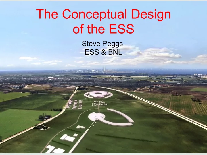
The Conceptual Design
- f the ESS
The Conceptual Design of the ESS Steve Peggs, ESS & BNL - - PowerPoint PPT Presentation
The Conceptual Design of the ESS Steve Peggs, ESS & BNL Concept to CDR (Feb 2012), TDR (Jan 2013), & on .... 120206 Steve Peggs 2 Neutrons in 2019 ! 5 MW beam power 2.5 GeV protons (H+) 2.9 ms pulses 14 Hz rep
120206 Steve Peggs 2
RAL+JAI, 120320 Steve Peggs 3
5 MW beam power 2.5 GeV protons (H+) 2.9 ms pulses 14 Hz rep rate 50 mA pulse current 704 MHz RF frequency < 1 W/m beam losses 7.5 MW upgradability? NO H- injection, no accumulator/compressor ring !
RAL+JAI, 120320 Steve Peggs
Many research reactors in Europe are aging & will close before 2020
There is a urgent need for a new high flux cold neutron source
present and imminent future need of short pulse users “Pulsed cold neutrons will always be long pulsed as a result of the moderation process”
4
120206 Steve Peggs
F1: Design Update, Prepare to Build, Construction, & Operations phases
5
RAL+JAI, 120320 Steve Peggs
Sweden, Denmark & Norway cover 50% of cost The other 14 member states covers the rest, with the European Investment Bank
6
RAL+JAI, 120320 Steve Peggs
7
Max-IV under construction
RAL+JAI, 120320 Steve Peggs
8
RAL+JAI, 120320 Steve Peggs
9
120206 Steve Peggs
F5: Preliminary neutron beamline and instrument layout, for the instruments in T4.
10
120206 Steve Peggs
F27: Left: A scorpion and a leaf. Right: Neutron image of scorpion made from two stitched partial scorpion images at 10.0 ̊A and 300 seconds [60].
11
120206 Steve Peggs
F47: Plan view sketch of bi-spectral beam extraction. The two outer guides are bi-spectral, while the central one is purely cold. Not to scale.
12
120206 Steve Peggs
F15: Proposed time structure use and instrument layout using a dual cold and thermal guide system [37].
13
RAL+JAI, 120320 Steve Peggs 14
120206 Steve Peggs
F31: General conceptual layout of the target station. The target monolith is shown at the left, with representative neutron beamlines on the right.
15
120206 Steve Peggs
F56: Proton beam dump and neutron beam catcher in the target station building.
16
RAL+JAI, 120320 Steve Peggs
17
How difficult can it be?
http://www.youtube.com/watch? v=ijWwfcw0FOo
Rotating tungsten disk target
1.50 m
0.08 m
0.5 Hz Target-to-neutron-lines
commissioned on Day 1
& below target
http://esss.se/linac/Parameters.html F48: Target Station monolith general view.
120206 Steve Peggs
F49: Schematic view of the first (blue) and second (green) safety barrier locations during normal power operation.
18
F32: Sketches of the target wheel. Top: Radial and azimuthal flow of helium around the slices. Bottom: Global geometry, showing the angular sectorisation into slices.
RAL+JAI, 120320 Steve Peggs 19
120206 Steve Peggs 20
Spokes Medium β High β DTL MEBT RFQ LEBT Source HEBT & Upgrade Target
2 m 5 m 1 m 19 m 75 m 117 m 200 m 163 m
75 keV 3 MeV 50 MeV 191 MeV 653 MeV 2500 MeV
352.21 MHz 704.42 MHz HS_2011_11_23
Orange items (such as the RFQ and the DTL) are normal conducting. Blue items (spoke resonators, medium & high-β elliptical cavities) superconducting. 2012 decisions, evolving beyond HS_2011_11_23::
Decisions about RFQ length, RFQ design current & MEBT design under way
120206 Steve Peggs
21
The upgrade guideline states that a power upgrade can be made by increadsing:
For the superconducting linac, the current can be doubled from 50 mA to 100 mA without changing the basic layout if the power of all RF sources can be doubled. Doubling the power of the RF sources can be done, in principle, by:
120206 Steve Peggs
F68: Schematic layout of the ion source & Low Energy Beam Transport.
22
F69: Measured ion source emittances for different values of microwave power and magnetic field.
Degree of development is already consistent with the ESS specs, i.e. nearly ready for a TDR.
120206 Steve Peggs
23
Beam Instrumentation:
profile measurement)
120206 Steve Peggs 24
F60: Emittance through RFQ. F61: Radial particle density distribution as a function of radius and distance along the RFQ.
Beam dynamics design at a rather advanced stage, but cross-check with more simulation codes; perform error analysis. Engineering design will be finished for the TDR Issue: RFQ length: as designed 5 m Long RFQ: small εL increase & high T. Is a smaller emittance a substantial reliability issue, compared with drawbacks? Shorter RFQ (3 m): fewer brazing/vacuum/cooling joints; less RF power; less expensive, easier to achieve requested tolerances.
120206 Steve Peggs
F62: RMS beam sizes in the HS_2011_11_23 lattice, from RFQ to the last elliptical cavity, for an initial 0.20 π mm mrad 4D waterbag distribution without space charge.
25
F63: Transverse particle density distribution along the HS 2011 11 23 linac, with the black contour representing the clear aperture.
120206 Steve Peggs
F72: Left: Emittance growth through the MEBT in the horizontal (red), vertical (blue) and longitudinal (green) planes. Right: RMS beam size envelopes.
26
F71: Compact MEBT layout, with 4 quadrupoles & 2 buncher cavs
There is no realistic MEBT design yet. MEBT induces some emittance growth. MEBT enables chopping and collimation. Recent decision to go “full function” Prototype where? Beam tests?
120206 Steve Peggs
Proposal : make a permanent test line in the MEBT: A beam stopper is needed for dedicated studies of the MEBT
27
RFQ
B S M
SLIT and Grid system
BCT BPM (position and TOF) Wire scanner BPM (chopping efficiency) Faraday cup (beam stopper) Buncher cavities Chopper Dump
120206 Steve Peggs
A movable diagnostic test bench would be useful for:
28
120206 Steve Peggs
29
Strong similarities to Linac4 at CERN. Preliminary beam dynamics calculations & EM design have been performed. Recent decision to design the extended DTL for 50 mA with emphasis on high reliability. Linac technology will have advanced so much by the time that ESS will be upgraded that it is not motivated to build the front-end for more than 50 mA today. It was also decided to defer the discussion about the RFQ design current to after the NC linac review in June. The DTL-to-spoke cavity transition energy will be increased to about 80 MeV.
120206 Steve Peggs
F75: Overall aspect of the double spoke cavity.
30
F76: Distribution of surface fields in the spoke cavity. Left: Electric. Right: Magnetic.
120206 Steve Peggs
F79: Cold tuning system for spoke resonators.
31
F80: Conceptual design of a 352 MHz spoke power coupler of 56 mm diameter and computed return loss S11 .
120206 Steve Peggs
F81: Geometry of the prototype high beta (β = 0.86) cavity.
32
F83: Elliptical cavity geometry and higher order mode performance. Left: Geometry of coupler-side end-group. Right: Lowest frequency TM monopole mode.
120206 Steve Peggs
F84: High beta elliptical cavity with a titanium helium vessel, and an integrated piezo tuner.
33
F85: Left: The CEA-Saclay 1 MW power coupler, with an
F86: Electric field distribution in the doorknob transition between rectangular & coaxial waveguides.
RAL+JAI, 120320 Steve Peggs 34
SPL/ESS A “half” cryomodule is being built & will be tested at SM18 in collaboration with CERN.
“2010 BASELINE” continuous elliptical cryomodules (LEFT)
RAL+JAI, 120320 Steve Peggs
35
“2011 HYBRID” layout is uused in HS_2011_11_23 A ~70K sleeve encloses (most cold) interconects, reducing heat load. Some interconnects may be left warm, e.g. to simplify beam instrumentation.
120206 Steve Peggs
F89: Typical segmented cryomodule, from the SNS.
36
F90: A continuous cryomodules with internal cryogenic lines - XFEL.
120206 Steve Peggs
Careful thought and a sophisticated design process indicates that the 2012 releases of the ESS lattice (May & Oct) will use segmented CMs
37
RAL+JAI, 120320 Steve Peggs
38
Transverse beta functions Increase smoothly
Longitudinal optics Represented by phase advance rate
Spokes Lo-beta High-beta
120206 Steve Peggs 39
Extrapolate these idealized optics to the real world:
Quality assurance, production testing, sorting, re-tuning, simulating?
F59: The power gained by a 50 mA beam in each cavity in the HS 2011 11 23 lattice [82]. Background colours indicate different cavity types and RF sources.
120206 Steve Peggs
F96: System block diagram of a klystron RF system, with one cavity per power source.
40
F99: Possible layout of a section
gallery, with one klystron per modulator.
120206 Steve Peggs
F64: Horizontal (red), vertical (blue) and longitudinal (green) RMS emittance in the HS_2011_11_23 linac, from the entrance to the RFQ to the last elliptical cavity.
41
120206 Steve Peggs
F67: Particles falling
the superconducting linac & getting lost in a case of unrealistically large RF amplitude ripple and phase jitter
42
F65: Acceptance (blue background) and matched beam (multi-coloured ellipse) at the entrance to the HS_2011_06_22 superconducting linac.
RAL+JAI, 120320 Steve Peggs
Radio-activation is unacceptable from losses larger than about 1 W/m. Intra-beam stripping is the dominant source (?) of beam losses in H- linacs like the SNS (0.2 W/m) - but not in the H+ ESS ! Other potential beam loss sources:
Confidently predicting the relative importance of loss mechanisms is a fundamental challenge to our ability to design multi-MW proton linacs. Resolve by 1) simulation & theory, 2) experiment (eg, SNS) ......
43
RAL+JAI, 120320 Steve Peggs
Higher Order Modes
Field Emission & Multipacting
Low Level RF
accumulate along the linac
44
RAL+JAI, 120320 Steve Peggs
45
Accelerator-to-Target
120206 Steve Peggs
F93: Top: The layout of the HEBT. Middle: RMS beam sizes – H (blue) & V (red). Bottom: Vertical dispersion function. Beam sizes & dispersion are based on envelope calculations.
46
120206 Steve Peggs
F94: The beam foot print obtained at the target from multi-particle simulations of 105
scale (representing particle density) in each case is scaled to the maximum value.
47
RAL+JAI, 120320 Steve Peggs
48
RAL+JAI, 120320 Steve Peggs
49
2.5 5.0-7.5 [**50] < 1
ESS [**50 mA in 2.9 ms pulses at 14 Hz] Finding #5: “The missions for Accelerator Driven Sub-critical (ADS) technology lend themselves to a technology development, demonstration & deployment strategy in which successively complex missions build upon technical developments of the preceding mission.” U.S. Dept. of Energy White Paper (2010).
RAL+JAI, 120320 Steve Peggs
up, with the Technical Design Report in Jan 2013.
construction, installation, commissioning & operations.
advantage” for P2B?
50