
SLIDE 1
1 / 20
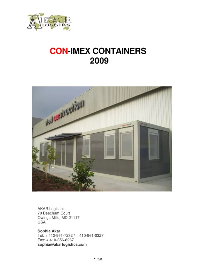
CON-IMEX CONTAINERS 2009
AKAR Logistics 70 Beecham Court Owings Mills, MD 21117 USA Sophia Akar Tel: + 410-961-7232 / + 410-961-0327 Fax: + 410-356-8267 sophia@akarlogistics.com
The proposed containers are "Flat-pack" type. Disassembled - - PDF document
CON-IMEX CONTAINERS 2009 AKAR Logistics 70 Beecham Court Owings Mills, MD 21117 USA Sophia Akar Tel: + 410-961-7232 / + 410-961-0327 Fax: + 410-356-8267 sophia@akarlogistics.com 1 / 20 GENERAL The proposed containers are
1 / 20
AKAR Logistics 70 Beecham Court Owings Mills, MD 21117 USA Sophia Akar Tel: + 410-961-7232 / + 410-961-0327 Fax: + 410-356-8267 sophia@akarlogistics.com
2 / 20
GENERAL
The proposed containers are "Flat-pack" type. Disassembled and reduced as "sandwich" made up of base, and roof chassis, connected by suitable metallic spacers. Wall panels, door and windows panels, finishing profiles, screws and bolts as well as the electrical preassembled installation will be placed inside the flat-pack package. This system has been particularly designed per 2.4mt x 6.0mt as a standard in order to reduce the transport space as well as quick and easy handling and can be produced in different sizes rather than the standard. Joining on adjacent sides to achieve a larger area, CON-IMEX CONTAINERS can also be built as two storey units. The CON-IMEX CONTAINERS have been designed so that they can be handled with forklifts or cranes and are suitable for truck, train or ship transportation.
3 / 20
BOTTOM CHASSIS The bottom chassis is made up of 2,5 mm thick sheet metal press-formed into profiles and welded to the four corner blocks.
bottom chassis strength material painting 250 kg/m² 2.5mm con-imex steel profiles all welded chemical treatment + 100 micron electrostatic powder dyed color RAL 7032
The floor surface consists of 18 mm thick OSB-3 (Oriented Strand Board), fixed to the omega profiles by means of self-threading screws and covered with PVC sheets glued at the top layer. The base insulation is made of 50 mm thick glasswool planks placed to the cross bars of the perimetric profile.
floor top layer board vapor barrier insulation protection 2mm vinyl flooring 18mm OSB-3 100 micron polyethylene 50mm glasswool 0.4mm galvanized sheet metal
4 / 20
ROOF CHASSIS The roof consists of a 2.5 mm sheet metal press-formed into profiles and welded to the four corner blocks. 0.8mm Galvanized steel sheet covering is at the top layer. The insulation is 50 mm glasswool planks and over it polyethylene vapour barrier is laid for vapour barrier. The ceiling will be covered with 8 mm thick white laminated chipboard. Roof frame will be painted with electrostatic powder paint.
top chassis strength material painting 100 kg/m² 2.5mm con-imex galvanized steel profiles all welded chemical treatment + 100 micron electrostatic powder dyed color RAL 7032 ceiling board vapor barrier insulation roof cover 8mm white laminated chipboard 100 micron polyethylene 50mm glasswool 0.8mm galvanized sheet metal
5 / 20
WALLS
The inner and outer wall surfaces are polyester dyed galvanized sheet metal with polyurethane inner core. Panels shall be tongue and groove joined and completed with dust and water proofing rubber seals.
45mm 40kg/m3 polyurethane sandwich panels. outer surface: 0.5mm RAL 9002 (outside) & RAL 9010 (inside) polyester dyed galvanized sheet metal inner surface: 0.5mm RAL 9002 (outside) & RAL 9010 (inside) polyester dyed galvanized sheet metal
Panel thickness: 45 mm External side plane sheet thickness: 0.5 mm Internal side plane sheet thickness: 0.5 mm
6 / 20
Four columns which are made of 2,5 mm thick steel sheet metal are electrostatic powder dyed. In order to connect the roof chassis to the base chassis columns are fixed by means of bolts. During the assembly phase, the panels are fixed to the upper roof profile by means of sliding joints easy placed at the bottom of the base guide U profile.
7 / 20
DOORS AND WINDOWS External door (850 x 2100 mm.) The door shall be mounted into the wall panel composed of a fixed frame and a wing frame made of Aluminium or PVC. Polyurethane panel is fixed into the door wing and shall be equipped with 4 hinges, dust and water- proofing gaskets. The external doors are opening outwards.
8 / 20
Windows (800 x 1200 mm.) The windows are Aluminum or PVC and, shall be fitted into the wall panel and equipped with 4/12/4 mm float, double glazing.
9 / 20
ELECTRICAL INSTALLATION
Electrical supply voltage provided 220 V
It shall consist of inlet composed of fixed plug 16 A connected to the main panel by means of a flexible cable 3x4mm2 or 5x4mm2 NYM. The cables shall be positioned indoors on ceiling and shall come out through the holes placed on roof profiles near the fixed plug. The fixed plug shall be mounted and fixed to their
electrical system shall not exceed 16 A measured in each single phase at the electrical system source.
It shall be made of self-extinguishing PVC and placed in suspended ceiling close to the external connection. Its colour shall be white RAL 9001.
10 / 20
GUARD HOUSES
11 / 20
OFFICE CONTAINERS
12 / 20
13 / 20
14 / 20
NERATOR CABINS
15 / 20
ABLUTION TRAILER
16 / 20
2 STOREY CONTAINERS Instead of placing two containers on top of each other, 2 Storey CON-IMEX CONTAINERS are built with a middle chassis acting as the floor of the first floor and the ceiling of the ground floor. The flatpack package is 115cm high.
17 / 20
TWO STOREY UNIT INSTALLATION
dismantled from the middle chasis. After the top layer is lifted , the package footings will be also dismantled from the roof chasis. The columns will be placed at 4 corners of the unit and the connections will be placed to the
them, will be mounted.. The columns will be placed to the middle chasis corner sockets and it is important that they are not mounted to the middle chasis before placing the top chasis on top of the columns. After the roof chasis is placed on the columns, the columns will be fixed to both middle and roof
dismantled.
connections to the upper chasis will be dismantled.
and the bloning will be made at 50%.
containers is crucial on the concrete blocks.
stripe of sticker will be mounted on the columns and chassis
placed adjacent to the first one and the two will be bloned from the holes on the columns to each other.
the second container, the third container will be erected and connected to the second.
18 / 20
the panels and will be hung and placed inside the U shaped panel runners on the bottom chasis. The galvanized hook will be checked for right placement to the 2.5cm notch of the above chasis.
half panels will be installed last.
longitudinal panels will be from panel to panel.
them(5cm galvanized U profiles with screws on them) will be fastened against the columns.
forced in place.
are tongue and groove joined.
corner profiles will be installed.
used in between and 20 cm wide flashing will be mounted.
top surface there will also be a rubber band installation.
19 / 20
20 / 20