
SLIDE 1
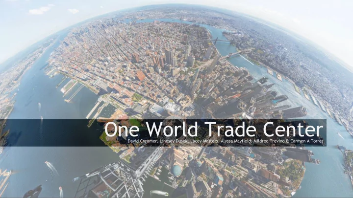
One World Trade Center
David Creamer, Lindsey Dusek, Lacey Masters, Alyssa Mayfield, Mildred Trevino & Carmen A Torres
"The tower is an open, welcoming building that both radiates - - PowerPoint PPT Presentation
One World Trade Center David Creamer, Lindsey Dusek, Lacey Masters, Alyssa Mayfield, Mildred Trevino & Carmen A Torres "The tower is an open, welcoming building that both radiates light and is filled with light. Our design team has
David Creamer, Lindsey Dusek, Lacey Masters, Alyssa Mayfield, Mildred Trevino & Carmen A Torres
"The tower is an open, welcoming building that both radiates light and is filled with light. Our design team has achieved our goal of creating a great urban place -- a building that serves the people who work in it, welcomes those who visit it, and plays an integral and vibrant role in the city that surrounds it."
Completion Date: 2013 Height to Architectural Top: 1,776 feet Total Area: 3,501,274 square feet Cost: US $3.9 billion Primary Use: Office Project Developer: The Port Authority of New York & New Jersey Architect: Skidmore Owings & Merrill LLP Structural Engineer: Sclaich Bergermann und Partner; WSP Cantor Seinuk; Leslie E. Robertson Associates MEP Engineer: Jaros, Baum & Bolles Main Contractor: Tishman Construction Project Manager: The Port Authority of New York & New Jersey Wind Consultant: RWDI Elevator Consultant: Jaros, Baum & Bolles
9/11 terrorist attacks Controversy arose People questioned whether to rebuild the towers as they were, whether they should come up with a new design, or whether any skyscraper should be built in the first place.
World Trade Center site in New York City, NY
Having previously been a target for terrorist attacks, architect David Childs felt it was necessary to make the skyscraper feel safe
Extra wide pressurized Stairs Structural redundancy Dense fireproofing Biochemical filters Backup emergency lighting Concrete protection for sprinkler systems Core wall Increased impact resistance Ultra strength concrete Pressurized to keep smoke out Enhanced elevators
“The project’s Structural Engineer used a combination
foundations, buttress slabs, core walls and columns”
One of the first times that BIM was being used in a project of this scale and complexity Skidmore, Owings and Merrill (SOM) is famously known to work with advanced BIM technology since the late 80s A combination of Revit, 3DS Max, and AutoCAD were used to produce the complex plans and renderings required to express the design
Helped implement MEP engineering into the model Decreased RFIs
Concrete core Steel Frame Prismatic glass around structural podium Curtain Wall Glass for the tower
“We believe that it sets a new standard for
New York City construction.” 14,000 psi concrete for podium and base 12,000 psi concrete for the structural core above podium
Prismatic glass around structural podium meant to make the concrete “fortress” seem more inviting. Emanates light because of the way the prism reflect light
1 WTC” (Freedom Tower) iterations Daniel Libeskind 1,776 spire Before approved,modified Larry Silverstein David Childs Childs different design turbines A hybrid of spire and turbines NY Police altered SOM took over radically changed today.
ceiling
services, retail, restaurants, and public transportation access.
challenges in term of site: Existing obstacles in terrain Subway vibrations Subway network and new hub Services must remain operational Partnership between disciplines Shear wall that runs the height of the building and down below grade must avoid complex veins of train lines.
Hybrid System combining a concrete core with a steel moment frame.
BASE
STEEL WORK
CONCRETE CORE
Stretches 20 stories high and is referred to as the podium.
Dimensions are 200’ x 200’, the same as the original Twin Towers
Blast Walls at the base fortify against truck bombings
Can withstand 14,000 pounds per square inch of pressure.
The Tower contains more than 40,000 metric tons of structural steel
Steel moment framing rises up from the solid base of the building
The moment frame wraps around all vertical and sloped perimeters, forming a tube system.
It resists lateral loads through bending of the frame elements. Paired with the concrete-core shear wall, the moment frame gives the building rigidity and redundancy while providing a column-free interior.
Provides support for gravitational loads as well as resistance to wind and seismic forces
Houses mechanical rooms and all means of egress.
Required 150,000 cubic meters of concrete
Floor system within the core is a cast-in-place concrete beam and flat slab system.
Uses high strength concrete to meet the demands imposed by the height and slenderness of the structure.
408 ft antenna Consists of mast and communication platform ringa Beacon at top sends out light beam
The spire is used for broadcasting and digital communication
The mast is protected by a fiberglass panel that resists wind load. Tetrahedral lattice ring supports media transmission equipment and braces eight radio frequency Kevlar guy cables that support the mast.
Frame to Interior Core (above base)
(exterior)
Rigid Frame
Beam Span
Cable guides pick up the loads
extra structure
structure meets the core
Design Goal Minimum Displacement = DL+LL
Force k
Stiffness Skyscraper design
F= k(Total Displacement)
the displacement or size of the deformation is directly proportional to the deforming force or load.