
SLIDE 1
Institute for Telecommunication Sciences
USTTI 2018 Monitoring & Measurements in Spectrum Management 19 - - PowerPoint PPT Presentation
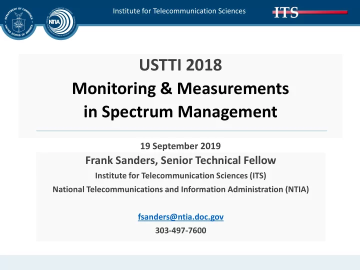
Institute for Telecommunication Sciences USTTI 2018 Monitoring & Measurements in Spectrum Management 19 September 2019 Frank Sanders, Senior Technical Fellow Institute for Telecommunication Sciences (ITS) National Telecommunications and
Institute for Telecommunication Sciences
Institute for Telecommunication Sciences
11 August 2017 Institute for Telecommunication Sciences 2
Institute for Telecommunication Sciences
11 August 2017 Institute for Telecommunication Sciences 3
Institute for Telecommunication Sciences
11 August 2017 Institute for Telecommunication Sciences 4
Institute for Telecommunication Sciences
11 August 2017 Institute for Telecommunication Sciences 5
Institute for Telecommunication Sciences
11 August 2017 Institute for Telecommunication Sciences 6
Institute for Telecommunication Sciences
11 August 2017 Institute for Telecommunication Sciences 7
Institute for Telecommunication Sciences
11 August 2017 Institute for Telecommunication Sciences 8
Institute for Telecommunication Sciences
11 August 2017 Institute for Telecommunication Sciences 9
Institute for Telecommunication Sciences
11 August 2017 Institute for Telecommunication Sciences 10
Institute for Telecommunication Sciences
11 August 2017 Institute for Telecommunication Sciences 11
Institute for Telecommunication Sciences
11 August 2017 Institute for Telecommunication Sciences 12
Institute for Telecommunication Sciences
11 August 2017 Institute for Telecommunication Sciences 13
Institute for Telecommunication Sciences
11 August 2017 Institute for Telecommunication Sciences 14
Institute for Telecommunication Sciences
11 August 2017 Institute for Telecommunication Sciences 15
Institute for Telecommunication Sciences
11 August 2017 Institute for Telecommunication Sciences 16
Institute for Telecommunication Sciences
11 August 2017 Institute for Telecommunication Sciences 17
Institute for Telecommunication Sciences
11 August 2017 Institute for Telecommunication Sciences 18
Institute for Telecommunication Sciences
11 August 2017 Institute for Telecommunication Sciences 19
Institute for Telecommunication Sciences
11 August 2017 Institute for Telecommunication Sciences 20
Institute for Telecommunication Sciences
11 August 2017 Institute for Telecommunication Sciences 21
Institute for Telecommunication Sciences
11 August 2017 Institute for Telecommunication Sciences 22
Institute for Telecommunication Sciences
11 August 2017 Institute for Telecommunication Sciences 23
Institute for Telecommunication Sciences
11 August 2017 Institute for Telecommunication Sciences 24
Institute for Telecommunication Sciences
11 August 2017 Institute for Telecommunication Sciences 25
Institute for Telecommunication Sciences
11 August 2017 Institute for Telecommunication Sciences 26
Institute for Telecommunication Sciences
11 August 2017 Institute for Telecommunication Sciences 27
Institute for Telecommunication Sciences
11 August 2017 Institute for Telecommunication Sciences 28
Institute for Telecommunication Sciences
11 August 2017 Institute for Telecommunication Sciences 29
Institute for Telecommunication Sciences
11 August 2017 Institute for Telecommunication Sciences 30
Institute for Telecommunication Sciences
11 August 2017 Institute for Telecommunication Sciences 31
Institute for Telecommunication Sciences
11 August 2017 Institute for Telecommunication Sciences 32
Institute for Telecommunication Sciences
11 August 2017 Institute for Telecommunication Sciences 33
Institute for Telecommunication Sciences
11 August 2017 Institute for Telecommunication Sciences 34
Institute for Telecommunication Sciences
11 August 2017 Institute for Telecommunication Sciences
Institute for Telecommunication Sciences
11 August 2017 Institute for Telecommunication Sciences
Institute for Telecommunication Sciences
frequency range.
11 August 2017 Institute for Telecommunication Sciences
Institute for Telecommunication Sciences
11 August 2017 Institute for Telecommunication Sciences
Institute for Telecommunication Sciences
11 August 2017 Institute for Telecommunication Sciences
Institute for Telecommunication Sciences
11 August 2017 Institute for Telecommunication Sciences
Institute for Telecommunication Sciences
11 August 2017 Institute for Telecommunication Sciences
Institute for Telecommunication Sciences
11 August 2017 Institute for Telecommunication Sciences
Institute for Telecommunication Sciences
11 August 2017 Institute for Telecommunication Sciences
Institute for Telecommunication Sciences
11 August 2017 Institute for Telecommunication Sciences 44