
SLIDE 1
Vibrational Gyroscopes in Instrumentation and in Creation
Robert Leland Oral Roberts University
rleland@oru.edu
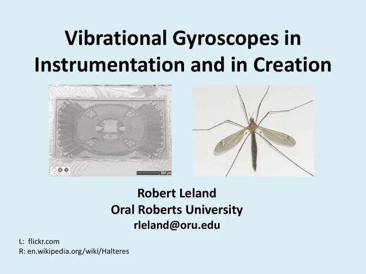
L: flickr.com R: en.wikipedia.org/wiki/Halteres
Vibrational Gyroscopes in Instrumentation and in Creation Robert - - PowerPoint PPT Presentation
Vibrational Gyroscopes in Instrumentation and in Creation Robert Leland Oral Roberts University rleland@oru.edu L: flickr.com R: en.wikipedia.org/wiki/Halteres Good design is a reflection of a wise designer. Even in the insects that God
Robert Leland Oral Roberts University
rleland@oru.edu
L: flickr.com R: en.wikipedia.org/wiki/Halteres
Vibrational gyroscopes are examples of this. They are found in both flies and man-made motion control systems. Vibrational gyroscopes illustrate important aspects of design in creation:
electro-mechanical systems
Wikipedia Commons www.nasa.gov/centers/dryden/multimedia/imagegallery/F-16AFTI/EC89-0016-20.html
There are no spinning parts. They measure their own rotation rate without reference to anything outside the body (inertial measurement). Used in attitude control (orientation) and navigation of aircraft and spacecraft. Gyroscopes are also found in iPhones, Wii controllers and flies.
Cassini Spacecraft www.jpl.nasa.gov
Drive Axis Sense Axis Mass M Spring K
The mass is driven to vibrate along the drive axis When the gyroscope rotates about an axis coming out of the screen, a Coriolis force creates a vibration along the sense axis. Rotation rate is determined from the sense axis vibration.
Combed fingers for driving and sensing motion. This gyro has two vibrating masses, like a tuning fork. Draper Tuning Fork Gyroscope
Acceleration/Vibration An Overview of MEMS Inertial Sensing Technology February 1, 2003 By: Jonathan Bernstein, Corning- IntelliSense Corp. Sensors Online Photo available as Figure 6 at www.sensorsmag.com/sensors/acceleration-vibration/an-
Diptera = 2 wings (instead of 4) Includes Drosophila (fruit flies) Rear wings are replaced with ‘posts’ called halteres. The halteres vibrate and function as gyroscopes. Crane Fly
Commons.wikimedia.org
Aerospace Technology Innovation Nov/Dec 1999
EEE Links Vol. 6 No. 1 Mar 2000 NASA Electronics Parts and Packaging Program
Rocks in one direction along the drive axis. The
sense axis
These sensors measure strain, (the fraction a surface is stretched or compressed). Strain provides a measurement of the bending of the supports, hence measuring the rocking of the post
Finite Element Analysis John Jackson
Sensors are formed by depositing and patterning a piezoelectric material (PNZT) on a silicon wafer
Haltere motion is sensed by five sensor fields called campaniform sensilla which sense strain like the University of Alabama gyro Most of these fields measure the back and forth motion of the halteres (drive axis) One field measures motion at a right angle to this vibration (sense axis) This last field sends signals directly to the motor neurons of the fly’s turning muscles
CSIRO ScienceImage 3237 Fly haltere.jpg Wikipedia Commons
“The critical role of the haltere in flight stability was first identified in 1714 by William Derham, who showed that a fly could not remain airborne if its tiny halteres were surgically removed. . .” Quote from: M.H. Dickinson,
Halteres identified as gyroscopes in 1938
Nature 141:919–920. (1938)
Show stable and unstable aircraft
Flies make rapid 90o turns in midair. These turns take about 1/20 of a second. In order to control these turns, flies sense rotation visually and with their halteres. The halteres appear to respond more quickly than the vision system. Experiments suggest: Visual sensing is used to initiate the turn. The halteres are used in ending the turn by making a quick counter-torque.
Possible trajectory
commons.wikimedia.org
vision system b1 muscle haltere
Complexity ≠ Good engineering design Successful, efficient, and reliable performance of tasks requiring complexity = Good engineering design
The Wright brothers achieved controlled, powered flight Controlled by Wilbur and Orville using wing warping. The body of the aircraft is extended, which increases stability.
General Dynamics F-16A AFTI 1.50- 2.07
It can move left
turning, banking,
down.
https://www.youtube.com/watch?v=iClN05EWuEY
www.nasa.gov/centers/dryden/multimedia/imagegallery/F-16AFTI/EC89-0016-20.html
http://tedxcaltech.com/content/michael-dickinson 1.25-1.44
The fly is capable of making complex responses to predators. The fly must determine the presence and position of a predator, estimate the time to respond, and initiate a complex flight sequence involving large changes in both orientation and direction. This all happens literally in the blink of an eye, and requires coordination of sensors, brain function and muscles.
Insect wings sweep back and forth at different angles and create a leading edge vortex (air rotation) above the wing that produces upward lift forces Most aircraft wings are airfoils that use streamlined airflow to create a lower pressure above the wing producing lift.
en.wikipedia.org
Forward Stroke Backward Stroke
Wikipedia Commons
Power muscles move the wings back and forth without direct control of beating from the brain (design efficiency) Steering muscles contract quickly to alter the hinge joints of the wings to create turns
www.flickr.com
en.wikipedia.org
Antenna: Can sense wind Eyes: Fastest visual system on earth Ocelli: Eyes, function unknown Halteres: Sense rotation Brain: About 100,000 neurons (design efficiency) Wing sensors: can sense changes in shape of the wing
commons.wikimedia.org
“When considering the control of complex aerial behaviors, it is impossible to disentangle the aerodynamics of flapping from the mechanics of the wing hinge, the physiology of the flight muscles, or the properties of sensory-motor circuits in the brain.
45:274–281 (2005)
God’s design in nature involves the successful coordination of complex interconnected systems.
www.flickr.com
www.flickr.com
Design of a MEMS gyroscope considers both the final product and the process to make it.
iPhone 4 Gyroscope
Computer Aided Design software is linked to the fabrication process.
en.wikipedia.org
Haltere development is controlled by a single gene: Ultrabithorax (Ubx). Without this gene, they develop into wings. Halteres develop from flat imaginal discs in the larva. During metamorphosis, these discs are extended so the center of disk becomes the far end of the haltere. Drosophila imaginal discs
en.wikipedia.org
Disc from leg en.wikipedia.org
Insect flight control systems display amazing engineering design. God’s design in nature includes achieving survival goals, integration into a larger system, and the ‘fabrication’ process. Insect flight control was recognized as displaying God’s wisdom in creation long before creation-evolution debates. Negative stereotypes of people who pull wings off flies should be reconsidered.
Micro Air Vehicle
en.wikipedia.com www.flickr.com
Attributes of God from His Works of Creation, 1914, London.
Diptera, Philos Trans R Soc Lond [Biol] 233:347–384 (1948) J.A. Bender, M. H. Dickinson, A comparison of visual and haltere- mediated feedback in the control of body saccades in Drosophila melanogaster, J Exp. Biol. 209, 4597-4606 (2006)
in Fruit Flies, Integr. Comp. Biol., 45:274–281 (2005)
Electrotonic Input to a Steering Motor Neuron in the Blowfly, Calliphora, J. Neurosci., 16(16):5225–5232 (1996)
http://tedxcaltech.com/content/michael-dickinson This presentation gives a very clear description of the complexity of flight control in flies, and their nervous systems. It also contains videos of the fly experiments.
How Flies Fly
Gyroscopic sensing: body rotations lead to torsion in flapping, flexing insect wings, J. Royal Society Interface, Jan 28, 2015.