1. Raising and stabilizing the lakes waterline level; 2. Preventing - - PowerPoint PPT Presentation

1 raising and stabilizing the lake s waterline level 2
SMART_READER_LITE
LIVE PREVIEW

1. Raising and stabilizing the lakes waterline level; 2. Preventing - - PowerPoint PPT Presentation

Papers for the Request for Information (RFI) for Salton Sea Water Importation Projects by California Natural Resource Agency - PowerPoint Presentation - March 9, 2018, Indio, CA Author: Nikola N. Lakic, Graduate Engineer Architect,


slide-1
SLIDE 1

Papers for the

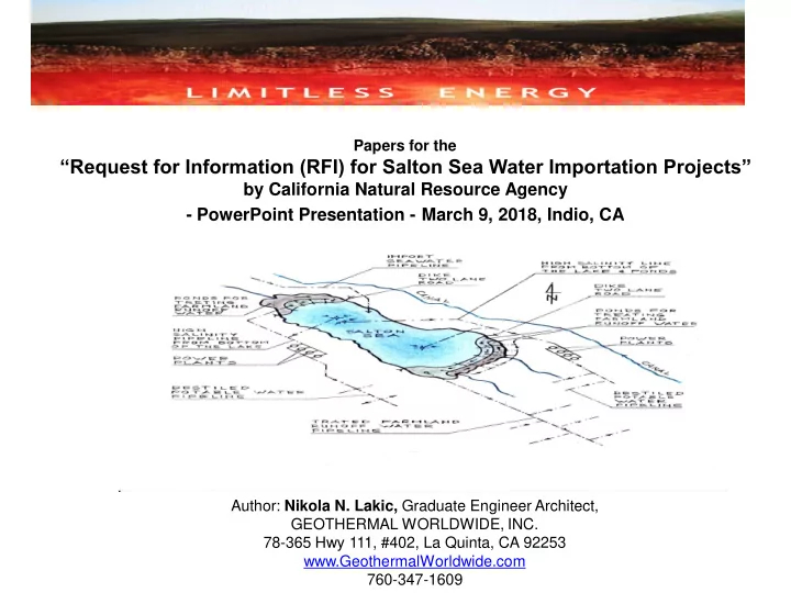
“Request for Information (RFI) for Salton Sea Water Importation Projects”

by California Natural Resource Agency

  • PowerPoint Presentation - March 9, 2018, Indio, CA

Author: Nikola N. Lakic, Graduate Engineer Architect, GEOTHERMAL WORLDWIDE, INC. 78-365 Hwy 111, #402, La Quinta, CA 92253 www.GeothermalWorldwide.com 760-347-1609

slide-2
SLIDE 2

OVERVIEW OF THE SALTON SEA SITUATION (I)

  • The Salton Sea is California’s largest lake and is presently 50 %

saltier than the Ocean. The Salton Sea is a “terminal lake,” meaning that it has no outlets. Water flows into it from several limited sources but the

  • nly way water leaves the sea is by evaporation.
  • The lake is shrinking exposing the lake bed and precipitating higher

salinity levels and environmental issues as well as a serious threat to its multi- billion-dollar tourist trade.

  • Under the terms of the Quantification Settlement Agreement (QSA) the

lakes decline is set to accelerate starting in 2018. About the 1/3 of inflow water from the canal will be diverted to San Diego and Coachella Valley.

  • Runoff water from nearby agricultural fields which contains fertilizers,

pesticides and other pollutants from Mexicali contaminate Salton Sea and make it an undesirable tourist destination especially for beach goers.

GEOTHERMAL WORLDWIDE, INC. EXECUTIVE SUMMARY:

slide-3
SLIDE 3

OVERVIEW OF THE SALTON SEA SITUATION (II)

  • The lake is 35 miles long, 15 miles wide, and is located south of Palm

Springs in a basin 230 feet below sea level.

  • The Earth’s crust at the south end of the Salton Sea is relatively thin.

Temperature in the Salton Sea Geothermal Field can reach 680 ºF (360 ºC) less than a mile below the surface.

  • There have been many complains and studies about consequences

for our community if a solution for the Salton Sea is not found .

  • There have been several proposals involving importing seawater, but

they failed to address the salinity balance and feasibility of the project. It was wishful conventional thinking – implying canals, tunnels, pipelines without addressing the practicality of its implementation and how to pay for it.

  • This proposal is quite different - it incorporates in final comprehensive

design, several patented technologies – that have not been accessible to the authors of previous proposals.

GEOTHERMAL WORLDWIDE, INC.

slide-4
SLIDE 4

OBJECTIVES OF THE ENCLOSED PROPOSAL FOR RESTORATION OF THE SALTON SEA

  • 1. Raising and stabilizing the lake’s waterline level;
  • 2. Preventing further pollution of the lake and treating farmland’s runoff waters with

natural and plant-based filtration systems – mangrove tree and alike;

  • 3. Providing wildlife sanctuary;
  • 4. Equalizing salinity of the salty terminal lake (Salton Sea) water with salinity of

the Ocean.

  • 5. Providing conditions for tourism and making Salton Sea a renewed recreational

destination;

  • 6. Harnessing prevalent geothermal source of the Salton Sea Geothermal Field

(SSGF) for generation of electricity; and as a byproducts

  • 7. Production of potable water and lithium;

GEOTHERMAL WORLDWIDE, INC.

slide-5
SLIDE 5

PROJECT DESCRIPTION

This proposal has an architectural element which harmoniously incorporates several patented technologies in a functional self-sustaining organism.

  • Phase I - Connecting the Salton Sea with the Ocean (presented are 5 Routs - corridors)

with a pipeline 48” (5 pipelines on uphill route and 1 pipeline on downhill route);

  • Phase II - Building two main dikes - One in northern and one in southern part of the

Salton Sea and several secondary dikes for forming ponds (wetland) for treatment of farmland’s runoff waters.

  • Phase III - Building one power plant using (SCI-GHE) system at one of selected sector;
  • Phase IV - Building several more power plants using (SCI-GHE) system - one in three

selected sector; and

  • Phase V - Continued buildup of additional power plants using (SCI-GHE) system at

each selected sector;

GEOTHERMAL WORLDWIDE, INC.

slide-6
SLIDE 6

DESALINIZATION OF THE SALTON SEA (I):

  • The desalinization of the Salton Sea and salt balance are the primary issues of

this proposal.

  • In order to compensate for evaporation of about 1.25 million acres/feet per year it

has to be inflow at least 1.25 million acres/feet per year.

  • By separating the lake into three sections with two main dikes we can treat

existing inflow and reuse it for farmland, which otherwise would be useless for farmland as it merge with the salty water of the lake.

  • By separating farmland’s runoff waters from the central part of the lake, we can fill

the central part of the lake with seawater and gradually reduce salinity by extracting higher salinity water from bottom of the lake.

  • High salinity water (brine) has higher density and has tendency to accumulate at

the lowest point(s) at the bottom of the lake where we can access it, pump it up and used in a new design of geothermal power plants for generation of electricity, and as byproducts produce potable water and lithium.

GEOTHERMAL WORLDWIDE, INC.

slide-7
SLIDE 7

DISALINIZATION OF THE SALTON SEA (II):

  • High salinity water (brine) can be use for forming new geothermal reservoirs

in the areas where new geothermal power plants (Scientific Geothermal Technology) are proposed for better conduction of the heat from hot rocks to first heat exchanger.

  • Optionally, high salinity brine can be use for filing existing geothermal reservoirs;
  • As an option - We could pump out high salinity water from bottom of the lake

with pipeline 24” diameter and disperse it into vast Ocean: A few miles offshore near Carlsbad there is a trench called “Carlsbad Canyon” through which high salinity water would slide slowly into depth of the Ocean and find its way to join existing currents in the vast ocean without negative effect on marine life.

  • Optionally, we can oxygenate brine on the way to the “Carlsbad Canyon” by

injecting air into pipeline in several locations, by compressors.

  • Hyper saline water – brine - is in sync with natural occurrence in oceans and

together with temperature difference the main engine in currents circulation in Oceans - called “deep ocean currents” or thermohaline circulation.

GEOTHERMAL WORLDWIDE, INC.

slide-8
SLIDE 8

Dimensions of the Salton Sea - Google map

GEOTHERMAL WORLDWIDE, INC.

slide-9
SLIDE 9

Geothermal Map – Salton Sea area - Temperatures at dept of 3.5 km

GEOTHERMAL WORLDWIDE, INC.

slide-10
SLIDE 10

GEOTHERMAL WORLDWIDE, INC.

Route # 1 – Map - Importing seawater from the Ocean to the Salton Sea

Route # 1

  • Importing seawater from the Gulf of

California – corridor: San Felipe through Mexicali, Mexico, to the Salton Sea;

  • Elevation to overcome is 35‘ (10 m);
  • Pipeline distance is about 150 mile;
  • Cost estimate for pipeline: $1.7 B;
  • Cost estimates for TOS: $184.8 M;
  • Generated hydro power: 27.3 MWh;
  • Generated solar power: 1,058 MWh;
  • Revenue from TOS: $114,349,320;
  • Revenue from hydro: $13,759,200;
  • Revenue total: $128,108,520;
  • This route also deals with the “Other

Country Issues” – treaty – purchase of seawater – risk involved, etc.

slide-11
SLIDE 11

GEOTHERMAL WORLDWIDE, INC.

Route # 1 – Plain view

Route # 1

  • Route #1 – corridor: Salton Sea
  • San Felipe (Gulf of California);
  • The Route # 1 has distance of

about 150 miles with preferred topography which has an advantage in pipeline cost.

  • Assumption $600 per linear foot.

One mile 5,280 ‘ x $600 = $3,168,000; => $3,168,000 x 450 miles relatively flat terrain (50 miles x 5 pipelines + 50 miles x 3 pipelines + 50 miles 1 pipeline) = $1,425,600,000;

  • The final cost might increase 20% to

about $1.7 billion.

  • If implemented a single outflow

pipeline 24” the final cost might increase 30%.

slide-12
SLIDE 12

GEOTHERMAL WORLDWIDE, INC.

Route # 1 – Cross-sectional view

  • Terrain of the Route #1

(corridor: Salton Sea - Gulf of California) is suitable and would be the least expensive option.

  • There is the “Other Country Issue”;
  • Even if treaty with Mexico are

reached and route established, I would recommend implementation

  • f one of the USA corridor too.
  • It would reduce dependency and

risk associated with the “other countries issues”.

  • It would be relatively small

investment in comparison to the revenue and benefits that whole project would generate in the future.

slide-13
SLIDE 13

Plain view of a schematic diagram of an alternative pipeline route connecting Salton Sea with Gulf of California, Mexico

  • Redirection of the New River 318 and

Alamo River 328 on Mexican side of the border with two gates 392 and 393 to flow towards Laguna Salada 394;

  • Requires relatively inexpensive earth

work (a few miles cut) 397 west of Mexicali, Mexico. ;

  • Optional route 396 bypassing Laguna

Salada 394 on the way to the Ocean;

  • the amount of water for the farmland

from All-American Canal can be controlled with valves 536 to be used

  • nly as necessary with sprinkler system

preventing formation of the runoffs water from farmlands entering the Salton Sea;

  • This option requires treaty with Mexico

to secure long-term interest of both countries.

GEOTHERMAL WORLDWIDE, INC.

slide-14
SLIDE 14

Alternative pipeline system associated with route connecting Salton Sea with Gulf of California, Mexico

  • System designed for more efficient

water conservation to accommodate water restriction and supply to southern section 206 – the wildlife sanctuary;

  • The amount of water for the farmland

from All-American Canal can be controlled with valves 536 to be used

  • nly as necessary with sprinkler system

preventing formation of the runoffs water from farmlands entering the Salton Sea;

  • Three main pipelines; eastern branch

531; central branch 532; and western branch 533; and secondary pipelines 534 extending from each of three main branches;

  • Control valves 536 on beginning and

control valves 537 on their ends.

GEOTHERMAL WORLDWIDE, INC.

slide-15
SLIDE 15

Enlarged southern part of the Salton Sea – wildlife sanctuary

GEOTHERMAL WORLDWIDE, INC.

  • The southern section of the lake 206

(wild life sanctuary) with an area 415 surrounded with a levy (dike) - two lain road 416, to form dry land 415 and secure development of a conventional geothermal power plant 427 at the area

  • f known geothermal reservoir;
  • If needed, the waste material from

power plant 300 can be diluted with water from pipelines 332, 335 or 337 before being injected into geothermal reservoirs.

  • Three main pipelines 531, 532 and 533

with control valves 537 for providing and circulating water in the southern section of the lake 206 (the wild life sanctuary).

  • There is a restaurant on the pier;
  • There are islands for birds 147;
slide-16
SLIDE 16

Plan view of a typical dike-pier intersection

  • The main dikes (two lane roads)

divides lake into three sections – preventing pollution of the central section of the lake providing conditions for tourism;

  • Secondary dikes forms ponds for

collecting and treating farmland’s runoff water and providing wildlife sanctuary – wetland;

  • Ponds are dig in “V” shape to

provide slope and deep points for segregation of higher density water which is selectively pumped out and used in the power plants;

  • There is a restaurant on the pier and

parking places for visitors;

  • There is airport for amphibian airplans;

GEOTHERMAL WORLDWIDE, INC.

slide-17
SLIDE 17

Cross-sectional view 89’-89” taken near a typical dike-pier intersection

  • The main dikes (two lane roads)

divides lake into three sections – preventing pollution of the central section of the lake and providing conditions for tourism;

  • Wetlands are planted with mangrove

trees or alike for natural filtration

  • f water;
  • Ponds are dig in “V” shape to

provide slope and deep points for segregation of higher density water which is pumped out and used in the power plants;

  • The injection well 426 can be used for

depositing waste material from power plant 300 with high salinity water through pipeline 428 into depleting geothermal reservoir.

  • There is a restaurant on the pier;

GEOTHERMAL WORLDWIDE, INC.

slide-18
SLIDE 18

Enlarged northern part of the Salton Sea – wildlife sanctuary

GEOTHERMAL WORLDWIDE, INC.

  • The main dikes (two lane roads)

divides lake into three sections – preventing pollution of the central section of the lake and providing conditions for tourism;

  • Pipelines 538 and 539 distributing

water to secondary pipelines 534 using sprinkler system for final distribution of water to farmland.

  • The amount of water for the farmland

can be controlled with valves 536 and 537 to be used only as necessary;

  • There is a restaurant on the pier;
  • Possible location of a Hotel Resort 540

with a section in the Salton Sea with the tower 550 to be built on manmade island 560 which contain a mechanism for generation of waves for surfing;

slide-19
SLIDE 19

GEOTHERMAL WORLDWIDE, INC.

Plain view of a typical Power Plant

  • 300 – Power Plant about 500

meters diameter;

  • 30 – Wells;
  • 380 – Power Units;
  • 200 – Control Center;
  • 290 – Processing Building;
  • 274 – Potable water pond;
  • 210 – Heat Exchange system;
  • 325 – Railroad track;
slide-20
SLIDE 20

GEOTHERMAL WORLDWIDE, INC.

  • A method for harnessing geothermal energy

for generation of electricity by using complete closed loop heat exchange systems combined with on-board drilling apparatus.

  • The first heat exchanger of the closed loop

system is lowered at heat source and second heat exchanger is coupled into boiler / evaporator of the Power Unite.

  • Salty water from the Salton Sea is injected

into boiler / evaporator to the level “H”.

  • Salty water is heated by heat exchanger and

steam is produced which enters pistons and generator, which generates electricity.

  • The power unit has a condenser which is

cooled with additional closed loop system.

  • Geothermal fluid and/or saturated brine is

circulated around first heat exchanger with an

  • n-board in-line-pump to minimize heat flux.
  • Drilling can continue as needed in search for

hot rocks until equilibrium is reached.

Schematic cross-sectional view of a Power Unite

slide-21
SLIDE 21

GEOTHERMAL WORLDWIDE, INC.

Cross-sectional longitudinal view of the Secondary In-Line-Pump / Generator

  • The In-Line-Pump / Generator is

an electromotor cylindrical shape and is inserted as a repetitive segment in the pipeline.

  • As a shaft of the rotor it has a

hollow cylinder with continues spiral blades inside hollow cylinder / shaft.

  • The Secondary In-Line-Pump /

Generators are a subsequent segments in the “Split & Join” and “Delta” mini Power Plants having gradually more exposed continuous spiral blade providing smaller openings in the middle of the cylinder as speed of fluid gradually decreases.

  • It yields a maximum flow rate with

limited diameter.

slide-22
SLIDE 22

GEOTHERMAL WORLDWIDE, INC.

Cross-sectional frontal view of the Primary and Secondary In-Line-Pump / Generator

  • In order to harness maximum

energy from the fall, the Primary Generator at the bottom of the fall, have continuous spiral blades, inside the hollow shaft, less exposed with bigger openings in the middle of the cylinder / shaft.

  • The subsequent segments - the

In-Line-Generators - in the section “C” (Delta Power Plant) have gradually more exposed continuous spiral blades with smaller openings in the middle

  • f the cylinder / shaft as speed
  • f fluid gradually decreases.
slide-23
SLIDE 23

GEOTHERMAL WORLDWIDE, INC.

  • A method for harnessing geothermal energy

for generation of electricity by using complete closed loop heat exchange systems combined with on-board drilling apparatus.

  • The first heat exchanger of the closed loop

system is lowered at heat source and second heat exchanger is coupled into boiler / evaporator of the Power Unite.

  • Salty water from the Salton Sea is injected

into boiler / evaporator to the level “H”.

  • Salty water is heated by heat exchanger and

steam is produced which enters pistons and generator, which generates electricity.

  • The power unit has a condenser which is

cooled with additional closed loop system.

  • Geothermal fluid and/or saturated brine is

circulated around first heat exchanger with an

  • n-board in-line-pump to minimize heat flux.
  • Drilling can continue as needed in search for

hot rocks until equilibrium is reached.

Schematic cross-sectional view of a Power Unite

slide-24
SLIDE 24

GEOTHERMAL WORLDWIDE, INC.

Cross-sectional view of a solar panel assembly

  • A Thermo Optical Solar (TOS) panel

assembly 610 and its attachment system to the pipeline 400.

slide-25
SLIDE 25

GEOTHERMAL WORLDWIDE, INC.

A side view of the solar panel assembly and its attachment system to the pipeline

  • A side view of the solar panel assembly

610 and its attachment system to the pipeline 400 and its lifting mechanism 612 in horizontal position;

  • The condenser 660 consist of bended

metal pipeline 662 and connectors 627 which connect closed loop line of the thermo optical solar system 567 and 700;

slide-26
SLIDE 26

GEOTHERMAL WORLDWIDE, INC.

A perspective view of a pipeline with solar panel assemblies attached to the pipeline in combination with a line of alternative solar system aside pipeline

  • Perspective view of a pipeline with solar

panel assemblies 610 attached to the pipeline in combination with a line of an alternative “thermo optical solar system” 700 aside pipeline.

slide-27
SLIDE 27

GEOTHERMAL WORLDWIDE, INC. Summary of the Preliminary Analyzes of Route #1

  • Route #1 --- Corridor: San Felipe - Mexicali, Mexico, - Salton Sea.
  • Elevation to overcome is 35 ‘ (10 m);
  • Pipeline distance is about 150 miles;
  • Cost estimate for pipeline: $1.7 billion;
  • Cost estimate for TOS: $184.8 million;
  • Route #1 would generate hydropower: 27.3 MWh;
  • The Thermo Optical Solar System installed on pipeline would generate

1,058.79 MWh;

  • Revenue generated from the Thermo Optical Solar

(TOS) System installed on pipeline Route #1 would be at least $114,349,320 per year;

  • Revenue generated from the “Delta” hydro power plant would be

$13,759,200 per year;

  • Revenue total: $128,108,520 per year;
slide-28
SLIDE 28

GEOTHERMAL WORLDWIDE, INC. Summary of the Preliminary Analyzes of Route #2

  • Route #2 Corridor: Oceanside - Temecula – San Jacinto (existing tunnel) –

Cabazon - Salton Sea;

  • Elevation to overcome is 1,600‘ (488 m);

2 cascades each with 279 m drop and 6uphill pumping stations;

  • Pipeline distance is about 160 miles;
  • Cost estimate for pipeline: $3.32 billion;
  • Cost estimate for TOS: $200 million;
  • Energy needed for operation of the pipeline: 134.5 MWh;
  • The Thermo Optical Solar System installed on pipeline would generate

1,058.79 MWh;

  • Remaining 924.30 MWh can be sold to the grid;
  • Revenue generated from the Thermo Optical Solar (TOS) System installed on

pipeline Route #2 would be at least $99,824,400 per year;

slide-29
SLIDE 29

GEOTHERMAL WORLDWIDE, INC. Summary of the Preliminary Analyzes of Route #3

  • Route #3 Corridor: Oceanside - Temecula - San Jacinto - Beaumont –

Salton Sea.

  • Elevation to overcome: 2,700‘ (823 m).

3 cascades each with 297 m drop and 9 uphill pumping stations;

  • Pipeline distance: about 170 miles;
  • Cost estimate for pipeline: $3.5 billion;
  • Cost estimate for TOS: $209.44 million
  • Energy needed for operation of the pipeline: 275.7 MWh;
  • The Thermo Optical Solar System(TOS) installed on the Route #3 pipeline

can generate 1,124.97 MWh;

  • Remaining 849.27 MWh can be sold to the grid;
  • Revenue generated from the Thermo Optical Solar (TOS) System installed on

pipeline Route #3 would be at least $91,721,160 per year;

slide-30
SLIDE 30

GEOTHERMAL WORLDWIDE, INC. Summary of the Preliminary Analyzes of Route #4

  • Route #4 Corridor: Oceanside - Temecula - Borrego - Springs –.Salton Sea.
  • Elevation to overcome is 3,600‘ (1,097 m);

4 cascades each with 292 m drop and 11 uphill pumping stations;

  • Pipeline distance: about 100 miles;
  • Cost estimate for pipeline: $2.22 billion;
  • Cost estimate for TOS: $123,200,000 million;
  • Energy needed for operation of the pipeline: 380 MWh;
  • The Thermo Optical Solar System installed on route #4 pipeline can generate

661,7 MWh;

  • Remaining 281.7 MWh can be sold to the grid;
  • Revenue generated from the Thermo Optical Solar (TOS) System installed on

pipeline Route #4 would be at least $30,423,600 per year.

slide-31
SLIDE 31

GEOTHERMAL WORLDWIDE, INC. Summary of the Preliminary Analyzes of Route #5

  • Route #5 Corridor: Long Beach – Whitewater - Springs – Salton Sea.
  • Elevation to overcome: 2,700‘ (823 m);

3 cascades each with 297 m drop and 9 uphill pumping stations;

  • Pipeline distance: about 200 miles;
  • Cost estimate for pipeline: $4.118 billion;
  • Cost estimate for TOS: $246,400,000 million;
  • Energy needed for operation of the pipeline: 275.7 MWh;
  • The Thermo Optical Solar System installed on route #5 pipeline can

generate1,323.49 MWh;

  • Remaining 1,047.80 MWh can be sold to the grid;
  • Revenue generated from the Thermo Optical Solar (TOS) System installed on

pipeline Route #5 would be at least $113,162,400 per year