Colorimetric Determination of Nitrogen Content In this experiment we - - PDF document

colorimetric determination of nitrogen content
SMART_READER_LITE
LIVE PREVIEW

Colorimetric Determination of Nitrogen Content In this experiment we - - PDF document

ICTP Winter College Xindi Wang Colorimetric Determination of Nitrogen Content In this experiment we will use colorimetric reagents for testing nitrogen levels in fish tanks to determine the concentrations of ammonia and nitrate in aqueous


slide-1
SLIDE 1

ICTP Winter College Xindi Wang 1

Colorimetric Determination of Nitrogen Content

In this experiment we will use colorimetric reagents for testing nitrogen levels in fish tanks to determine the concentrations of ammonia and nitrate in aqueous solutions.

As Assemble le th the colo lori rimete ter:

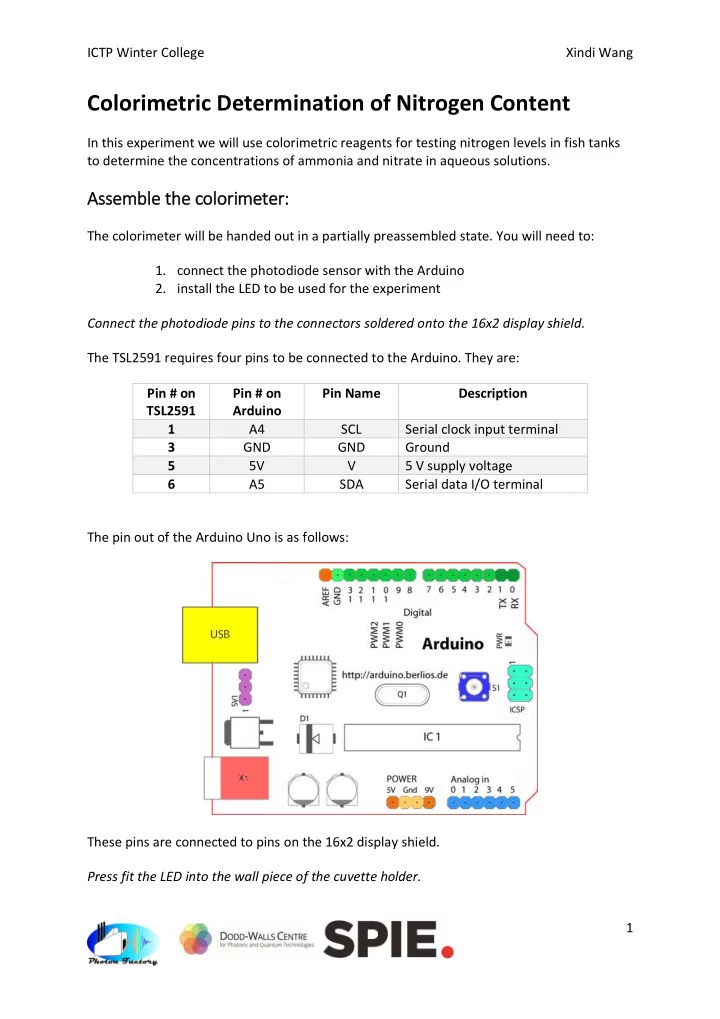
The colorimeter will be handed out in a partially preassembled state. You will need to:

  • 1. connect the photodiode sensor with the Arduino
  • 2. install the LED to be used for the experiment

Connect the photodiode pins to the connectors soldered onto the 16x2 display shield. The TSL2591 requires four pins to be connected to the Arduino. They are: Pin # on TSL2591 Pin # on Arduino Pin Name Description 1 A4 SCL Serial clock input terminal 3 GND GND Ground 5 5V V 5 V supply voltage 6 A5 SDA Serial data I/O terminal The pin out of the Arduino Uno is as follows: These pins are connected to pins on the 16x2 display shield. Press fit the LED into the wall piece of the cuvette holder.

slide-2
SLIDE 2

ICTP Winter College Xindi Wang 2 The LED has been connected to the appropriate resistor and can be press fit into the remaining wall piece of the cuvette holder. Slide the wall piece in and place the lid on top to create a dark chamber for our photometry experiment. Take care and be gentle when inserting the jumper cable into the pins on the display shield: the connection may be stiff and you could push the pin out if you push too hard, or it may not contact if you don’t insert it all the way. One trick is to use a spare pin to loosen the jumper cable first before plugging in to the display shield.

Photo tomete ter r opera rati tion

The photometer uses the “UP” “DOWN” and “LEFT” buttons on the display shield. In addition, you can reset the photometer at any point by pressing “RST”. Button Description UP Turns LED on Down Turns LED off LEFT First press acquires a blank reading (I0) and throws up a prompt to insert sample, pressing again acquires a value (I) and calculates the absorbance based on Beer’s law 𝐵 = −𝑚𝑝𝑕10 ( 𝐽 𝐽0 )

Colo lori rimetr try

Working in groups of 6 or 7:

  • 1. Connect one colorimeter to power and switch on LED
  • 2. Use the marked vials in your API water testing kit to measure out 5 mL of each

concentration of the ammonium nitrate standard solution, and one of the water sample and transfer to test tube

  • 3. Open one set of API nitrate test reagent
  • 4. Shake reagent bottles for ~30 seconds
  • 5. Add ten (10) drops of reagent #1 to each test tube, shake for ~5 seconds to mix
  • 6. Add ten (10) drops of reagent #2 to each test tube, shake for one (1) minute to mix

thoroughly

  • 7. Wait for four (4) minutes for colour to develop
  • 8. Fill a cuvette with some water
  • 9. Acquire a blank measurement
  • 10. Empty cuvette, rinse out water droplets with some drops of the contents of the test

tube

  • 11. Fill cuvette with contents of test tube, acquire absorbance value
  • 12. Record the concentration of the standard, the absorbance value
slide-3
SLIDE 3

ICTP Winter College Xindi Wang 3

  • 13. Repeat steps 8-12 until you have absorbance values for all four (4) standards and the

sample

  • 14. Repeat steps 4-13 using the ammonium test reagents, using EIGHT (8) drops instead
  • f ten (10) as specified on the bottle.

Bac ackgr ground

Colorimetry is a simple technique for determining the concentration of a coloured solution. Nitrate and ammonia containing solutions are colourless, so various reagents are used to produce a colour changing reaction where the analyte is the limiting reagent.

Reagents nts:

There are a variety of tests for nitrate based on Griess reagents. All of them involve reduction of nitrate (NO3-) to nitrite (NO2-) and subsequent reaction with aromatic compounds such as NEDD to form coloured solutions. In our case, the specific formulation

  • f the reagents are proprietary to API, but literature suggests that NO2- reaction with

sulphanilamide and subsequent reaction with a yellow NEDD produces a red compound with extensive conjugation and strongly absorbing in the green region of the visible spectrum (λmax = 550 nm). Tests for ammonia are based on the Bethelot reaction of ammonia with salicylate and nitroferricyanate to produce a green solution that absorbs strongly in the red region of the visible spectrum (λmax = 625 nm).

slide-4
SLIDE 4

ICTP Winter College Xindi Wang 4

Col

  • lori
  • rimetry

try

The absorption spectrum of the NEDD has λmax ~ 425 nm and is distinct from the absorption band of the product, λmax = 550 nm. By choosing a green LED with λemission = 530 nm we can measure the absorbance of the product independently. We can fit our data using a simple regression algorithm in Excel. From here, we can interpolate the absorbance of the sample to obtain the concentration and the related error.

0.2 0.4 0.6 0.8 1 1.2 1.4 1.6 1.8 2 300 350 400 450 500 550 600 650 700

Normalised spectra

Normalised absorbance spectrum Normalised LED spectrum y = 0.0235x + 0.0473 R² = 0.9965 0.00 0.05 0.10 0.15 0.20 0.25 0.30 0.35 0.40 0.00 2.00 4.00 6.00 8.00 10.00 12.00

Absorbance Concentration of standard solution (ppm)

Calibration Curve

slide-5
SLIDE 5

ICTP Winter College Xindi Wang 5

Trouble Shooting

Turning on device reads “No sensor found/ Check Wires”: There is a problem with the wires connecting the TSL sensor to the Arduino. Check that the pins don’t move when you push on them and that the solder pads are not shorted (that the solder doesn’t overflow onto other pads). The pins on the display shield are loose: Apply some flux to the pad where the pin has come loose, wait for it to set. Solder the pin back onto the pad. Buttons are unresponsive: The buttons return a unique analogue value: if (adc_key_in < 50) return btnRIGHT; //btnRIGHT = 0 if (adc_key_in < 150) return btnUP; //btnUP = 100 if (adc_key_in < 350) return btnDOWN; //btnDOWN = 256 if (adc_key_in < 550) return btnLEFT; //btnLEFT = 408 if (adc_key_in < 1000) return btnSELECT; //btnSELECT = 640 The values may change over time. Run upload and run the code called test-buttons.ino and

  • pen the serial monitor on the Arduino IDE. The values printed to the window change when

a button is depressed and you should record them and change the values in basic- photometer-v2.ino so the brackets fall in the right place.