Comparison for spent fuel behavior of PWR and SMRs Gyujae Nam 1 , - - PDF document

β–Ά
comparison for spent fuel behavior of pwr and smrs
SMART_READER_LITE
LIVE PREVIEW

Comparison for spent fuel behavior of PWR and SMRs Gyujae Nam 1 , - - PDF document

Transactions of the Korean Nuclear Society Virtual Spring Meeting July 9-10, 2020 Comparison for spent fuel behavior of PWR and SMRs Gyujae Nam 1 , Jong-Dae Hong 2 , Youho Lee 1 *, 1 Seoul National University, 1 Gwanak-ro, Gwanak-gu, Seoul 08826,


slide-1
SLIDE 1

Comparison for spent fuel behavior of PWR and SMRs

Gyujae Nam1, Jong-Dae Hong2, Youho Lee1*,

1Seoul National University, 1 Gwanak-ro, Gwanak-gu, Seoul 08826, Republic of Korea 2Korea Atomic Energy Research Institute, 989-111 Daedeokdae-Ro, Yuseong-Gu, Daejeon 34057, Republic of

Korea leeyouho@snu.ac.kr

  • 1. Introduction

While most of fuel simulation studies are conducted to investigate steady-state and accident behavior, relatively small attention has been given to the spent fuel behavior of existing PWRs. A limited number of studies addressed the pre-disposal spent fuel behavior

  • f existing LWRs [3]. It can be inferred from these

studies that the behavior of spent fuels is largely affected by its steady-state operation history, including fission gas generation, and cladding embrittlement such as oxidation, and hydrogen pick

  • up. This would naturally mean that there exists a

substantial difference of spent fuel behavior between existing LWRs and SMRs. Yet, no study, to the authors’ knowledge, has been conducted to address the spent fuel behavior difference, hence resulting management strategies and implications, of existing LWRs and SMRs. This study aims at exploring the pre-disposed spent fuel behavior

  • f

existing PWRs and some representative SMR designs, in order to illuminate the potential difference in their management strategies based on key safety threatening conditions. Fuel rod simulations that integrates steady-state, wet storage in spent fuel pool, and dry-storage were conducted using modified FRAPCON-4.0. The FRAPCON-4.0 has been modified in this study to properly capture key behavior unique to spent fuel. Comparisons were made among the existing PWR and selected SMRs, and the key differences that may affect the spent fuel failure modes are highlighted.

  • 2. Methods

Spent fuel behavior can be simulated mostly as an extension of steady-state fuel modeling. Yet, there are a few fuel behavior models that need to be modified for spent fuel simulation. These are (A) fission gas release, (B) cladding creep rate, and (C) pellet swelling due to self-radiation [3]. FRAPCON-4.0, by default, provides an option for dry storage simulation. However, it only accounts for the cladding creep rate among the aforementioned three required modifications for proper dry-storage fuel simulation. Hence, it is decided in this study to update FRPACON-4.0 with modifications and assumptions necessary for spent fuel simulation. They are:

  • 1. Fission gas release

A past investigation conducted by U.S NRC clearly demonstrates that no appreciable fission gas release takes place in spent fuel pellet at temperatures below 1000K [1]. Therefore, the modified code suppresses any fission gas release from spent fuel pellets at temperatures below 1000K.

  • 2. Pellet swelling rate

The fuel pellet continues to swell after discharging due to self-radiation. Raynaud et al., provides the best- estimate for fuel pellet swelling after discharge based

  • n various past experimental studies. The best

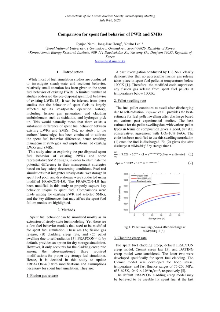
estimate for the pellet swelling data with various pellet types in terms of composition gives a good, yet still conservative, agreement with UO2-10% PuO2. The code has been modified to use this swelling correlation (1) once the fuel is discharged. Eq (2) gives dpa after

discharge at 60Mwd/kgU by storage time t.

βˆ†π‘ 𝑏0 = 3.528 Γ— 10βˆ’3 Γ— (1 βˆ’ π‘“βˆ’8.492π‘’π‘žπ‘)(𝐢𝑓𝑑𝑒 βˆ’ 𝑓𝑑𝑒𝑗𝑛𝑏𝑒𝑓) (1) dpa = 1.1742 Γ— 10βˆ’2 Γ— 𝑒7.2246Γ—10βˆ’1 (2)

Fig 1. Pellet swelling (βˆ†a/ao) after discharge at 60Mwd/kgU [3]

  • 3. Cladding creep rate

For spent fuel cladding creep, default FRAPCON creep model, Ciemat creep law [5], and DATING creep model were considered. The latter two were developed specifically for spent fuel cladding. The Ciemat model was developed for hoop stress, temperature, and fast fluence ranges of 75-250 MPa, 633-693K, 0~9 Γ— 1021n/cm2, respectively [5]. The default FRAPCON cladding creep model may be believed to be useable for spent fuel if the fast

Transactions of the Korean Nuclear Society Virtual Spring Meeting July 9-10, 2020

slide-2
SLIDE 2

neutron flux term is correctly adjusted for spent fuel. Yet, questions still remain in terms of its applicability for spent fuel simulation because the model has not been validated against the spent fuel cladding data. The Dating uses a creep model specific to spent fuel

  • cladding. The default FRAPCON creep model uses

effective stress, not hoop stress. Effective stress and hoop stress have a ratio of approximately 1.08 during dry storage.

Fig 2. Cladding creep strain rate at (A)400oC, (B)300oC [5]

Among these three candidates, the Dating model is considered most conservative from the viewpoint of gap closure with pellet swelling. That is, the low creep rate with the fuel rod pressure being higher than the external pressure (1 atm) gives a faster gap closure with the given pellet swelling rate. Hence, promoting PCMI with the highest likelihood, the dating model would yield the most conservative stress level in the

  • cladding. In such a context, this study uses the Dating

Creep model.

  • 4. Temperature during dry storage

The model developed by Feria et al [5] was employed for the fuel temperature during dry storage. The cladding temperature(T) drop during dry storage is given by Eq. (3) [5]:

T = βˆ‘ 𝑏𝑗 βˆ— exp(βˆ’π‘π‘— βˆ— πΆπ‘£βˆ’π‘‘ βˆ— 𝑒) + 298 (3)

2 𝑗=1

Bu is the discharge burn-up (MWd/kgU), and t is a dry storage time(years) [5]. The values for Eq. (3) parameters are summarized in Table 1.

Table 1 Parameters for cladding temperature calculation

Parameter Value 𝑏1(K) 𝑏2(K) 𝑐1(yearsβˆ’1MWd/kgUc) 𝑐2(yearsβˆ’1MWd/kgUc) c 264.95 110.05 3.78 68.12 1.88

  • 5. Suppression of Oxidation and Hydrogen Pickup

during dry storage The code has been modified to suppress oxidation and hydrogen pickup during dry storage, as can be anticipated.

  • 3. Simulation Cases

A conventional PWR fuel pin, SMART fuel pin [4], and NuScale fuel pin [2] were simulated using the modified FRAPCON-4.0 throughout the entire pre- disposal lifetime. The used parameters are summarized in Table 2.

Table 2. Cladding temperature during dry storage

1Axial power distribution of LWR is assumed 2Time dependent power history of LWR is assumed 3Linear power history is assumed

  • 4. Comparisons of Spent fuel behavior

Highlights of fuel simlation results and comparisons among selected reactors are dissused below. In this simulation, 0 years is the time of discharging fuel, and 5 years of wet storage and 100 years of dry storage are followed. 4.1 Temperature The peak temperature of dry storage was set to 400oC to comply with the regulation criteria for dry storage. Yet, it is noteworthy that this temperature can change with a further verification on hydride-reorientation

Parameter LWR NuScale SMART

Plenum length(cm) 52.5 13.49 16.6 Cladding

  • outer radius (mm)
  • thickness (mm)
  • material

9.49 0.57 Zr-4 9.50 0.61 M5 9.5 0.64 Zr-4 Fuel active length (m) 3.66 2.0 2.0 U-235 enrichment 5.96 4.95 4.95 Burn-up (MWd/kgU) 62 62 26 Fill gas

  • pressure (MPa)
  • composition

2.41 He 100% 1.58 He 100% 2.25 He 96%, Ar 4% Operating time(day) 1476 3500 1000 Linear heat generation (kW/m) Axial power distribution 20.1 8.2 11.9 Present Absence1 Present Time dependent power history Present Absence2 Absence3

Transactions of the Korean Nuclear Society Virtual Spring Meeting July 9-10, 2020

slide-3
SLIDE 3

mechanisms for SMRs. As can be seen in Fig. 3, the cooling rates are different for different discharge burnups.

20 40 60 80 100 120 300 350 400 450 500 550 600 650 700

Temperature(K) Storage time (yr) LWR, NuScale SMART

Fig 3. Cladding temperature during dry storage

4.2 Fuel rod plenum pressure Fuel rod pressure of wet and dry storage is largely affected by the amount of fission gas released during steady-state operation. The steady-state fission gas release is dictated by burnup and temperature. As can be seen in Fig. 4, LWR and NuScale yields similar level of peak plenum pressure at ~7MPa while SMART gives ~5.4 MPa.

20 40 60 80 100 1 2 3 4 5 6 7 8

Plenum pressure(MPa) Time (yr) LWR NuScale SMART

Fig 4. Fuel rod plenum pressure

4.3 Gap thickness When dry storage begins, the gap thickness increases due to the cladding strain increased. On the other hands, pellet swelling makes the gap thickness

  • decrease. If the gap closure occurs, cladding is subject

to high hoop stress, and it leads to cladding failure. In the simulations, gap thickness inceases at the start of dry storage, and slightly decreases. However, the gap closure does not occur in 100 year dry storage(Fig. 5).

20 40 60 80 100 50 100 150 200 250 300

Gap thickness(microns) Time (yr) LWR NuScale SMART

Fig 5. Fuel and cladding mechanical gap thickness

4.4 Cladding oxidation and hydrogen-pickup Cladding oxidation and resulting hydrogen-pickup are determined by steady-state operation. As can be anticipated, conventional LWR, characterized by higher burnup and power, gives significantly thicker

  • xide scale formation and hydrogen-pick up amount.

These embrittlement factors stay with the fuel throughout the entire spent fuel lifetime, implying the importance of addressing the steady-state behavior from the viewpoint of spent fuel management. It can be inferred that both SMR fuels can ease the spent fuel management with less embrittlement. When wet storage begins, most hydrogen is precipitated. Due to high temperature, the hydrogen dissolved at the start

  • f dry storage, but after 100 years, most hydrogen is

precipitated again.

Fig 6. Cladding (A)oxide thickness and (B)hydrogen-

pickup and precipitation 4.5 Stress states of cladding The hoop stress levels are shown in Fig. 7 (A). It is notable that cladding experiences a non-negligible level of stress (26, 20 ,15 for PWR, NuScale, and SMART, respectively) during wet storage due to a considerable pressure difference between the plenum and the pool. The vacuum drying upon the initiation

  • f dry storage sharply increase stress level. The peak

hoop stress levels for 400oC 61, 48 ,35 for PWR, NuScale, and SMART, respectively. Stress biaxiality is known to affect the threshold stress for hydride

  • reorientation. It stays as ~2.1 for all fuels.

Transactions of the Korean Nuclear Society Virtual Spring Meeting July 9-10, 2020

slide-4
SLIDE 4

Fig 7. Cladding (A) hoop stress, (B)biaxiality

  • 5. Identification of key safety factors

Based on the obtained spent fuel behavior, conditions relevant to key failure modes of each wet and dry storage have been identified. For wet storage, structural integrity of embrittled cladding is a key fuel safety concern because highly embrittled cladding due to a considerable amount of precipitated hydrides at relatively low temperature (50oC) is subject to tensile

  • stresses. Based on the performed simulations, key fuel

states during wet storage are summarized in Table 3.

Table 3. Key conditions relevant to residual cladding ductility during wet storage

LWR NuScale SMART

Fuel rod plenum pressure [MPa] 3.1 3.0 2.4 Hoop stress [MPa] 26 20 15 Oxide scale thickness [microns] 80.4 14.7 28.2 Hydrogen pickup amount [wppm] 683 83 213 Hydrogen precipitated[wppm] 680 81 211 Gap closure Unclosed Unclosed Unclosed

Technical guideline on the retention of cladding ductility under the above conditions may need to be sought for any plausible abnormal events including mechanical impact due to earthquake and fire. Similarly, key fuel states during dry storage that need to be considered in terms of hydride reorientation are summarized in Table 4.

  • Table4. Key conditions relevant to hydride-orientation and

delayed hydride cracking during 100 years of dry storage

LWR NuScale SMART

Cooling Rate [oC/year] (avg, max, min) 7.87 7.87 39.73 2.67 2.67 3.27 0.58 0.58 0.40 Peak Fuel rod plenum pressure [MPa] 7.0 7.0 5.4 Peak hoop stress [MPa] 61 48 35 Stress biaxiality 2.1 2.1 2.1 Oxide scale thickness [microns] 80.4 14.7 28.2 Hydrogen pickup amount [ppm] 683 83 213 Hydrogen precipitation Half dissolved, Gradually increase Fully dissolved, Gradually increase Fully dissolved, Gradually increase Gap closure Unclosed Unclosed Unclosed

  • 6. Conclusion

Because SMR fuels are subject to less harsh operating conditions in steady state in terms of burnup, temperature, and resulting embrittlement, they can beckon the possibility of reducing some of key conservatisms in the spent fuel regulation. This also implies that a new regulatory guideline may be suitable for SMR spent fuels. The specific conditions relevant to investigating structural integrity of spent fuel in both wet and dry storage are attained as an

  • utcome of this study.

ACKNOWLEDGMENTS This work was supported by the Nuclear Safety Research Program through the Korea Foundation Of Nuclear Safety (KoFONS) using the financial resource granted by the Nuclear Safety and Security Commission(NSSC) of the Republic of Korea. (No. 1903004) REFERENCES

[1] Z. Talip , T. Wiss , V. Di Marcello , A. Janssen , J.-Y. Colle , P. Van Uffelen , P. Raison ,and R.J.M. Konings , Thermal diffusion of helium in 238Pu-doped UO2, Journal

  • f Nuclear Materials, Vol 445, pp.117–127, 2014

[2] TR-0816-51127, NuFuel-HTP2β„’ Fuel and Control Rod Assembly Designs, NuScale Power, LLC, January 2017 [3] Patrick A.C. Raynaud, and Robert E. Einziger, Cladding stress during extended storage of high burnup spent nuclear fuel, Journal of Nuclear Materials, Vol 464, pp304–312, 2015 [4] Chang, M. H., Yeo, J. W., Zee, Q. S.; Lee, D. J., Park,

  • K. B., Koo, I. S., Kim, H. C., and Kim, J. I., Basic design

report of SMART, Mar 2002 [5] F. Feria , L.E. Herranz, and J. Penalva, On the way to enabling FRAPCON-3 to model spent fuel under dry storage conditions: The thermal evolution, Annals of Nuclear Energy, Vol 85, pp.995-1002, 2015 Transactions of the Korean Nuclear Society Virtual Spring Meeting July 9-10, 2020