Compensation factor of Sensitivity on Gamma Camera for Incident Gamma - - PDF document

compensation factor of sensitivity on gamma camera for
SMART_READER_LITE
LIVE PREVIEW

Compensation factor of Sensitivity on Gamma Camera for Incident Gamma - - PDF document

Transactions of the Korean Nuclear Society Virtual Spring Meeting July 9-10, 2020 Compensation factor of Sensitivity on Gamma Camera for Incident Gamma Rays from a Boundary of the Field of View Jihwan Boo, Seoryeong Park, and Manhee Jeong *


slide-1
SLIDE 1

Compensation factor of Sensitivity on Gamma Camera for Incident Gamma Rays from a Boundary of the Field of View Jihwan Boo, Seoryeong Park, and Manhee Jeong*

Department of Nuclear and Energy Engineering, Jeju National University, Jeju 63243, Republic of Korea

*Corresponding author: mhjeong@jejunu.ac.kr

  • 1. Introduction

In addition to the ability to detect and identify radioactive material with gamma-ray detectors, the capability of imaging spatial radiation distributions provides essential information that can be utilized in various applications. To have a reconstructed image of that distribution, the planar coded aperture configuration which has a diverse pattern, such as the hexagonal uniformly redundant arrays (HURA) [1] or modified URA (MURA) [2], has been developed. However, the apertures mentioned above have a loss of sensitivity for sources that are off-axis [3]. This problem is because the mask attenuation increases for the aforementioned sources, leading to more attenuation at the boundary of the field of view (FOV). Consequently, the coded aperture system has a limited effective viewing angle. On the other hand, there has recently been the spherical aperture [4] developed for providing a near 4π isotropic FOV. Nonetheless, this model has difficulty in fabricating the aperture whose

  • paque zones are thick enough to absorb a high energy

gamma-ray (662 keV or 1170 keV). In this study, we have proposed a compensation factor of sensitivity on gamma camera based on the planar type mask. Monte Carlo N-Particle eXtended (MCNPX)-Polimi code was employed to evaluate the performance under many possible scenarios. Table I: System description MURA Mask Scintillator Material Tungsten (W, ρ = 19.3 g/cm3) Ce:GAGG (doped 0.5 mole%) Rank 11 (11 × 11 array) Pixel size 4.015 mm 4.2 mm Total size 8.43 × 8.43 cm2

(10.43 × 10.43 cm2 including border)

4.62 × 4.62 cm2 Thickness 2 cm 2 cm

  • 2. Methods and Results

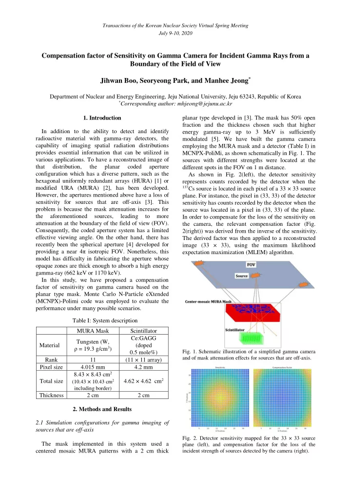
2.1 Simulation configurations for gamma imaging of sources that are off-axis The mask implemented in this system used a centered mosaic MURA patterns with a 2 cm thick planar type developed in [3]. The mask has 50% open fraction and the thickness chosen such that higher energy gamma-ray up to 3 MeV is sufficiently modulated [5]. We have built the gamma camera employing the MURA mask and a detector (Table I) in MCNPX-PoliMi, as shown schematically in Fig. 1. The sources with different strengths were located at the different spots in the FOV on 1 m distance. As shown in Fig. 2(left), the detector sensitivity represents counts recorded by the detector when the

137Cs source is located in each pixel of a 33 × 33 source

  • plane. For instance, the pixel in (33, 33) of the detector

sensitivity has counts recorded by the detector when the source was located in a pixel in (33, 33) of the plane. In order to compensate for the loss of the sensitivity on the camera, the relevant compensation factor (Fig. 2(right)) was derived from the inverse of the sensitivity. The derived factor was then applied to a reconstructed image (33 × 33), using the maximum likelihood expectation maximization (MLEM) algorithm.

  • Fig. 1. Schematic illustration of a simplified gamma camera

and of mask attenuation effects for sources that are off-axis.

  • Fig. 2. Detector sensitivity mapped for the 33 × 33 source

plane (left), and compensation factor for the loss of the incident strength of sources detected by the camera (right). Transactions of the Korean Nuclear Society Virtual Spring Meeting July 9-10, 2020

slide-2
SLIDE 2

2.2 Compensation of the strength of incident gamma rays

  • Fig. 3(a) and (c) shows reconstructed images that are

most intense at the center using MLEM algorithm, when five 662 keV gamma sources with different strength are located at different positions. This strength biasing problem in the images is due to the loss of sensitivity on the gamma camera for those sources that are off-axis. Tungsten mask leads to more attenuation

  • n the strength of sources located at the boundary of

the FOV. However, when the compensation factor was applied, as shown in Fig. 3(b) and (d), the strength of the sources in the images was corrected, proportional to each sources’ strength.

Fig.3. The reconstructed raw image (a) and interpolated image (c) using MLEM for 662 keV gamma sources with different strengths (0.1:0.2:0.3:0.4:0.5) at (−50, 0), (-25, 0), (0, 0), (25, 0), and (50, 0). The compensation factor was applied in the images (b, d) originally based on the images (a, c), respectively.

2.3 Energy windowing for correction of source positions When gamma sources located at an angle away from the axis, there is an increase in sensitivity on incident gamma-rays that are scattered from its incident direction due to the mask. Fig. 4(b) presents that the strength distribution of gamma sources was corrected as we expected when using the compensation factor. However, the spatial distribution of a source that is located at the near boundary of FOV deviates from its

  • wn position. In order to solve this problem, the

acquired data can be binned in energy windows ranging from 300 keV to 670 keV and reconstructed using MLEM, as presented in Fig. 4(c). As a result, the gamma camera can accurately point out the original source positions, although the weakest source does not appear.

  • Fig. 4. The reconstructed image (a) using MLEM for 662

keV gamma sources with different strengths (0.1:0.3:0.6) at (−45, -45), (0, 0), and (45, 45). The compensation factor was applied to both images (b, c) based on the image (a). When the image (b) used the counts in all energy spectrum, the image (c) employed the counts in the energy window (300 keV to 670 keV).

  • 3. Conclusions

In summary, these MCNP simulation study indicates that it is possible to compensate for the sensitivity on gamma camera for the sources positioned in the boundary of FOV. Furthermore, we can also correct the position for those gamma sources. We believe that the quality of images obtained by the gamma camera can be improved employing the compensation factor and energy windowing technique. REFERENCES

[1] M. J. Cieślak, K.A. Gamage, and R. Glover, Coded- aperture imaging systems: Past, present and future development–A review. Radiation Measurements, Vol. 92, pp.59-71, 2016. [2] R. Accorsi, Design of near-field coded aperture camera for high resolution medical and industrial gamma-ray imaging, Ph.D. Thesis, Cambridge, MA: Department of Nuclear Engineering, Massachusetts Institute of Technology, 2001. [3] M. Jeong, and M.D. Hammig, Comparison of gamma ray localization using system matrixes obtained by either MCNP simulations or ray-driven calculations for a coded-aperture imaging system. Nuclear Instruments and Methods in Physics Transactions of the Korean Nuclear Society Virtual Spring Meeting July 9-10, 2020

slide-3
SLIDE 3

Research Section A: Accelerators, Spectrometers, Detectors and Associated Equipment. Vol. 954, pp. 161353, 2020. [4] D. Hellfeld, P. Barton, D. Gunter, L. Mihailescu, K. Vetter, A Spherical Active Coded Aperture for 4π Gamma- Ray Imaging. IEEE Transactions on Nuclear Science, Vol.64, pp.2837-2842, 2017. [5] M. Jeong, G. Kim, MCNP-polimi simulation for the compressed-sensing based reconstruction in a coded-aperture imaging CAI extended to partially-coded field-of-view, Nuclear Engineering and Technology, https://doi.org/10.1016/j.net.2020.02.011 Transactions of the Korean Nuclear Society Virtual Spring Meeting July 9-10, 2020