DESIGN OF LIFTING OPERATION SYSTEM (HYDRAULIC SYSTEM-SPUD CAN - - PowerPoint PPT Presentation
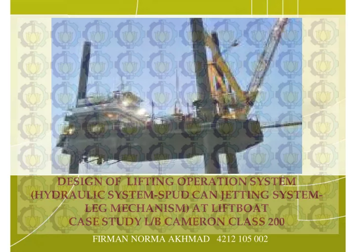
DESIGN OF LIFTING OPERATION SYSTEM (HYDRAULIC SYSTEM-SPUD CAN JETTING SYSTEM- LEG MECHANISM) AT LIFTBOAT CASE STUDY L/B CAMERON CLASS 200 FIRMAN NORMA AKHMAD 4212 105 002 PROBLEM DEFINITION a. How to design spud can jetting system to ease
PROBLEM DEFINITION
a. How to design spud can jetting system to ease spud can extraction from seabed before sail preparation of Liftboat with L/B cameron Class 200 as a case study ? b. How leg mechanism is working during the lifting of Liftboat with L/B cameron Class 200 as a case study ? c. How to design hydraulic system for lifting operation of leg/hull body of Liftboat with L/B cameron Class 200 as a case study?
SCOPE OF RESEARCH
a. Selection type of leg and mechanism system using on it and explanation how it work b. Piping and Instrument diagram of spud can jetting system c. Piping and Instrument diagram of hydraulic lifting system d. The stability of liftboat is not investigated in this thesis e. Ship strength is not investigated in this thesis
OBJECTIVE
a. Selection type of leg and mechanism system of Liftboat with L/B Cameron Class 200 as a case study b. Design of spudcan jetting system that technically capable for leg lifting preparation of Liftboat with L/B Cameron Class 200 as a case study c. Design of hydraulic system that technically capable for hull/leg lifting of Liftboat with L/B Cameron Class 200 as a case study d. Piping and Instrument diagram of hydraulic lifting system and spud can jetting system
METHODOLOGY
Start 1Books 2Journals 3 Thesis 4 Paper 5 Article Data Collection Identification and Problem Statement L/ B Cameron Class 200 General Arrangement Redrawing Literature Review Rules/ statutory/ standard Collection Design of the systems Lifting mechanism Hydraulic jack-up system Spud can jetting system Input Parameters
- 1. Selection of lifting
mechanism
- 2. Selection type of
legs
- 3. Explanation of lifting
mechanism
- 1. Selection of Jetting
Pump
- 2. Spud Can Jetting
Pressure
- 3. Pipe, fitting material
& instrument
- 4. Discharge
arrangement
- 1. Selection of
Hydraulic Pump along with other instruments
- 2. Design of hydraulic
system pressure
- 3. Selection of
pipes/ hoses, fittings and other supporting instruments Final Design Finish Accepttance: technically/ classification / statutory No Yes Conclusions
- 1. Detail Calculation
- 2. Detail Drawing (P&ID)
- 3. Technical Spec
INTRODUCTION TO LIFTBOAT
A liftboat, to differentiate with a conventional jackup drilling rig is defined as a self-elevating, self-propelled vessel equipped with at least one crane and with open deck space that can be used for multiple purposes.
Liftboat Perform Crane Operation Liftboat Perform Maintenance at Fixed Platform Liftboat at Windfarm Installation
Typical Liftboat Component : (US Patent US 6,523,491 B1)
- 14. Aft Leg
- 32. Rudder
- 30. Propeller
- 23. Deck House
- 11. Hull
- 21. Deck
- 26. Boom
- 29. Rigging
- 42. Horizontal surface
- 43. Inclined Surface
- 19. Recess
- 44. Vertical Surface
- 16. Spudcan/pad
- 45. Rake
- 25. Crane Support
- 24. Cab
- 28. Gantry
- 13. Leg Stbd
Typical Liftboat Component : (US Patent US 6,523,491 B1)
- 17. Aft Spudcan/pad
- 14. Aft Leg
- 11. Hull
- 23. Deck House
- 26. Boom
- 21. Deck
- 15. PS Spudcan
- 16. SB Spudcan
- 34. Upper surface
- 22. Support Crane
- 12. Portside Leg
- 12. Starboard Leg
- I. DESIGN OF LIFTING MECHANISM
- 1. Selection type of lifting mechanism which will be used
There are two popular methods in jacking system : 1. Yoke and Pin Jacking System A jacking system using yokes with pins, both operated by hydraulic cylinders, to engage with holes on the legs of the liftboat in order to raise
- r lower the hull in relation to the legs in the elevated condition or to raise
- r lower the legs in relation to the hull in the afloat condition. (ABS Guide
For Building and Classing Liftboat 2009, (Part.4, Chap.4, Sect. 1, 3.7) 2. Rack and Pinion Jacking System A jacking system using climbing pinions, most commonly driven by electric or hydraulic motors through a jacking gearbox, to engage with racks attached to the legs of the unit in order to raise or lower the hull in relation to the legs in the elevated condition or to raise or lower the legs in relation to the hull in the afloat condition (ABS Guide For Building and Classing Liftboat 2009, (Part.4, Chap.4, Sect. 1, 3.5)
1. Yoke and Pin Jacking System
Based on US Patent 8,425,155 B2 :
- Upper Yoke (no.6)
- Lower Yoke (no.7)
- Locking Pin (no.9, 9’)
- Hydraulic Cylinders (no.8)
- Cylinders for Locking Pin (no.10)
- Leg Holes (no.11A-11J)
- Jack House (no.5)
- Leg (3)
The locking pin (9’) at lower yoke (7) engage to leg hole (11D) by cylinder for locking pin (10), in vice locking versa the locking pin (9) at upper yoke in disengaging position. So when the load of ship weight of take by the lower yoke (7) then the cylinder (8) push the leg (3) downward. Now the cylinder is fully extend and ready to engage with leg hole (11G) and prepare to take over the load of ship weight.
How does it work ?
- 2. Rack and Pinion Jacking System A.
Based
- n US Patent
4,655,640 :
- Frame (no.14)
- Upper Cross Member (no.28)
- Upright Side Member (no.24,
26)
- Rack (no.16)
- Pinion (no.56, 58)
- Apart Side Cheek (no.50, 54)
- Means of Shaft (no.60)
- Piston Cylinder (no.64, 66,
68, 70)
- Cross Member (no.84)
- Support Frame (no.18)
- Pivot Joint Establishing Pin
(no.84, 86, 92, 94)
- Upper Wheel Support (no.34)
- Lower Wheel Support
(no.32)
- Platform (no.10)
- Box Portion / Housing
(no.98)
- Lock Element (no.100)
- Support Column / Leg
(no.12)
- Corner Portion (no.22)
- Central Portion (no.36)
- Side Portion (no.44)
- Mounting Ear (no.72)
- Side Plate Portion
(no.32)
- Lower End Member
(no.20)
How does it work ?
One pair of hydraulic cylinder 64, 66 or 68, 70 are retracted and the other pair is extended. As shown in Fig. Elevational View of Jacking System, The piston cylinders 64, 66 are retracted and piston cylinder 68, 70 on extended position. To lift up the platform (10), lower pinion is locked by the lock element (100) and upper pinion will left unlocked. Next, The cylinder 64, 66 are retracted while the upper piston (67, 70) is start to extended. When lower piston cylinder (64, 66) are retracted they will pull the platform (10) upwardly. The upper wheel support (34) is now being move upwardly by the lift force result by lower piston (64, 66).
- B. Based on US Patent 6,652,194 B2:
- Tower (no.40)
- Tubular Column (no.27)
- Rack (no.32)
- Piston Cylinder Unit (no.33)
- Engagement
/ Disengagement Means (no.35)
- Rack Engagement Member (no.34)
- Pivot Attachment (no.33p)
- Chord (no.26)
How does it work ?
There are three pairs of piston cylinder units (33a, 33b, 33c) each leg. To provide continuous linear motion, the piston/cylinder units (33a, 33b, 33c) of each set (31) and the engagement and disengagement
- f their
toothed rack engagement means (34) are phased so it their operation will be displaced in time.
There are two types of power sources for Fixed Jacking Systems, electric and hydraulic. Both systems have the ability to equalize chord loads within each leg. (Bennet & KeppelFELS, 2005) This type of jacking system is simple, hydraulic system which have hydraulic motor as actuator that will create rotary motion, then control of rotation will be adjust by planetary gear box, planetary gear box connected to pinion in mechanical
- connection. Rotary motion in pinion
will be change to linier motion by rack teeth attached to the leg.
- C. Based on GustoMSC Rack and Pinion System
- Teeth pinion
- Motor
- Planetary gearbox
- Tubular Column / Leg
- Rack
How does it work ? This type is selected
- II. DESIGN OF HYDRAULIC JACK-UP SYSTEM
- 1. Selection of Hydraulic Pump along with other instruments
1. Hydraulic Motor
No Jacking Vg Motor rpm Pressure Motor Condition (cm3/rev)
- Displ. (%)
(bar) Torque (Nm) 1. Raising hull 31.06 88.75 200 200 84.82 2. Raising leg 10.08 28.79 300 100 27.52
- 1. Maker
: Danfoss series 40 motor, M35 MV
- 2. Product type
: In-line, axial piston, variable, positive displ
- 3. Rotation
: Clockwise (CW) & counterclockwise (CCW)
- 4. Displacement
: 35 cm³ / rev.
- 5. System pressure
: Rated pressure 210 bar
- Max. pressure
345 bar
Specification :
- 2. Hydraulic Pump
Specification :
No Jacking Q req 4 units Vg rpm Pump Q supply 4 units Condition motor (l/min) (cm3/rev)
- Displ. (%)
motor (l/min) 1. Raising hull 27.61 41.21 750 89.79 27.82 2. Raising leg 13.44 13.44 1200 29.27 14.51
- 1. Maker
: Danfoss series 40 pump, M46 PV
- 2. Product type
: In-line, axial piston, variable, positive displ
- 3. Rotation
: Clockwise (CW) & counterclockwise (CCW)
- 4. Displacement
: 45.9 cm³ / rev.
- 5. System pressure:
: Rated pressure 345 bar
- Max. pressure
385 bar
- 3. Hydraulic Charge Pump
Specification :
Total charge flow requirements :
- 1. Leakage Requirement
= 29.5 gpm
- 2. Loop Flushing Requirement
= 24 gpm
- 3. Fluid Compressibility
= 9.09 gpm
- 4. Auxiliary Function
= 5 gpm Total = 67.6 gpm
- 1. Maker
: Danfoss Gear Pump Group 3, SNP3 75
- 2. Product type
: Gear pump, positive displ
- 3. Displacement :
74.4 cm³ / rev.
- 4. RPM
: Min. Speed 600
- Max. Speed
2500 5. System pressure: : Rated pressure 180 bar Peak pressure 200 bar
- 4. Hydraulic Brake
Specification :
Torque for brake : t = 13889.069 / 24 brake units = 579 Nm Brake capacity = 120% x
- Max. brake torque
requirement = 120% x 578.71 Nm = 694.45 Nm
- 5. Hydraulic Jacking Drive
Specification :
Jack-up drive requirement : For jacking Torque = 124253.8 Nm = 1099646.1 in-lbs Jacking rate = 44.73 Ton = 49.31 S-Ton For holding Torque = 149114.01 Nm = 1319659 in-lbs Holding rate = 59.65 Ton = 65.75 S-Ton 1. Maker Oerlikon Fairfield 2. Model S130 Jacking Drive 3. Specification Jacking
- Max. Torque
= 1,300,000.00 in-lbs
- Max. Jack rate
= 90.00 S-Ton Holding
- Max. Torque
= 2,330,000.00 in-lbs
- Max. Holding
= 158.00 S-Ton
Hydraulic Jack-up System P&ID
- 1. Selection of Jetting Pump
There are two in jacking system : 1. High Pressure Jetting System
- Flow rate = 25 m3/h
- Pressure = 80 bar
(Stability and Operation of Jackups 1993, Page 280)
2. Low Pressure Jetting System
- Flow rate = 180 m3/h
- Pressure = 12 bar
References : 1. Seajacks Hydra - Specification Sheet http://www.seajacks.com/pdfs/JW491%20Seajacks%20Hydra%20Specification%20Sheet.pdf 2. Seajacks Kracken - Specification Sheet http://www.seajacks.com/pdfs/Seajacks%20Kraken%20Brochure_lr.pdf 3. Seajacks Leviathan - Specification Sheet http://www.seajacks.com/pdfs/Seajacks%20Leviathan%20Brochure_lr.pdf 4. Seajacks Zarathan - Specification Sheet http://www.seajacks.com/pdfs/JW554%20Seajacks%20Zaratan%20Brochure.pdf Pump Specification : 1. Maker : Hamworthy 2. Model : CGC 125 3. Head : 140 m (max) 4. Capacity : 200 m3/h (max) 5. Type : Centrifugal Pump
- 2. Discharge Arragement at Spud Can
6-12 Nozzles (Stability and Operation of Jackups 1993, Page 279) 6-12 Nozzles (Stability and Operation of Jackups 1993, Page 279)
- 3. Selection of pipes, fittings and other supporting instruments
1. High Pressure Jetting System
- Flow rate = 25 m3/h
- Pressure = 80 bar
Main Line : 2 1/2 " SCH. 80 diameter pipe is selected (ASTM A 53) 2. Low Pressure Jetting System
- Flow rate = 180 m3/h
- Pressure = 12 bar
Main Line : 6" SCH 40 pipe is selected (ASTM A53 Carbon steel seamless) 3. Standard fitting components : strainer, pressure gauge, etc.
Spud Can Jetting System P&ID
PROGRESS IN PERCENTAGE
No Description Load (%) Realization (%) Progress (%) 1 Literature Review 20 100 20 2 General Arrangement Redrawing 5 100 5 3 Lifting M echanism 20
- a. Selection type of lifting mechanism
5 100 5
- b. Selection type of legs
5 100 5
- c. Explanation of lifting mechanism process
10 100 10 4 Design of Hydraulic J ack-up S ystem 35
- a. Selection of Hydraulic Pump along with
20 100 20
- ther instruments
- b. Design of hydraulic system pressure
5 100 5
- c. Selection of pipes/ hoses, fittings and other
10 100 10 supporting instruments 5 Design of Spud Can J etting S ystem 20
- a. Selection of Jetting Pump
5 100 5
- b. Discharge Arragement at Spud Can
5 100 5
- c. Design of Spud Can Jetting Pressure
5 100 5
- d. Selection of pipes, fittings and other
5 100 5 supporting instruments Total (%) = 100
CONCLUSIONS AND SUGGESTIONS
1. Conclusion a. Rack and pinion type is used as leg mechanism at L/B Cameron Class design b. Spudcan jetting system at L/B Cameron Class design at two pipe ring :
- High pressure : 80 bar @ 25 m3/h
- Low pressure : 12 bar @ 180 m3/h
c. Hydraulic jacking system at L/B Cameron Class design at two operating pressure :
- Lifting hull: 200 bar @ 88.75% motor disp. and 89.79% pump disp.
- Lifting leg : 100 bar @ 28.79% motor disp. And 29.27 % pump disp.
With configuration each leg : 2 pumps and 8 motors d. Main Component P&ID of hydraulic jacking system are hydraulic pump, hydraulic motor, charge pump and hydraulic brake. Main component P&ID of spudcan jetting are high pressure pump and low pressure pump 2. Suggestion a. The research with other type of hydraulic system is possible b. For those who interest in gear system, the variety in rack and pinion system make the possibility to be used as a research c. Research in geotechnical engineering especially in offshore which has relation to spud can jetting system is only a few, so to make deeper research in this field consultation to the expert is required.