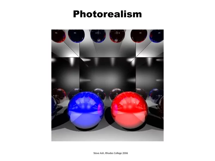
Photorealism Steve Ash, Rhodes College 2006 Planes Plane equation - - PowerPoint PPT Presentation

photorealism
SMART_READER_LITE
LIVE PREVIEW

Photorealism Steve Ash, Rhodes College 2006 Planes Plane equation - - PowerPoint PPT Presentation

Photorealism Steve Ash, Rhodes College 2006 Planes Plane equation a*x + b*y + c*z + d = 0 The triple N(a,b,c) is a vector that is perpendicular to the plane If N is also a unit vector, then for any point P(x p ,y p ,z p ) a*x p + b*y p


slide-1
SLIDE 1

Photorealism

Steve Ash, Rhodes College 2006

slide-2
SLIDE 2

Planes

Plane equation a*x + b*y + c*z + d = 0 The triple N(a,b,c) is a vector that is perpendicular to the plane If N is also a unit vector, then for any point P(xp,yp,zp) a*xp + b*yp + c*zp + d = distance from P to the plane N(a,b,c)

slide-3
SLIDE 3

Planes

Plane equation a*x + b*y + c*z + d = 0 POV specification plane { <a, b, c> d [ pigment (texture or color) ] [ material properties ] [ bump map (optional) ] } N(a,b,c)

slide-4
SLIDE 4

Ray-Plane Intersection

Plane equation a*x + b*y + c*z + d = 0 Ray equation p = source + t*direction px = sx + t*dx py = sy + t*dy pz = sz + t*dz Common point a*x + b*y + c*y + d = 0 a*(sx + t*dx) + b*(sy + t*dy) + c*(sz + t*dz ) = 0 t = ? could have 0 or 1 solutions (ray may be parallel to the plane)

slide-5
SLIDE 5

Plane Texture Mapping

Find any two vectors U, V such that N, U, V are mutually perpendicular Find a point Q that is on the plane N Q P(x,y,z) U V

slide-6
SLIDE 6

Plane Texture Mapping

Find any two vectors U, V such that N, U, V are mutually perpendicular Find a point Q that is on the plane N Q P(x,y,z) U V Compute Q = -d * N u = QP * U v = QP * V Note – Q is indeed on the plane a*Qx + b*Qy + c*Qz + d = ??? N*Q + d = N*(-d*N) + d =

  • d*(N*N) + d =
  • d*1 + d = 0

However, u and v are not in the range [0..1], so in the image i = u*width % width j = v*height % height

slide-7
SLIDE 7

Plane Bump Mapping

Use (i, j) and U, V that were computed for Texture Mapping

slide-8
SLIDE 8

Triangle Meshes

slide-9
SLIDE 9

Triangle Meshes

POV specification mesh { source { filename.pov } scale <sx, sy, sz> // multiply component-wise translate <tx, ty, tz> // add component wise [ pigment (texture or color) ] [ material properties ] [ bump map (optional) ] }

slide-10
SLIDE 10

Triangle Meshes

POV specification mesh { source { filename.pov } scale <sx, sy, sz> // multiply component-wise translate <tx, ty, tz> // add component wise [ pigment (texture or color) ] [ material properties ] [ bump map (optional) ] } x y z 10 10 10 source specification: (flat) triangle v1 v2 v3 color

triangle { <0, 0, 0>, <0, 10, 0>, <10, 0, 0> pigment {color rgb<1, 0, 0>} } triangle { <0, 10, 0>, <10, 10, 0>, <10, 0, 0> pigment {color rgb<1, 0, 0>} } triangle { <0, 0, 10>, <10, 0, 10>, <0, 10, 10> pigment {color rgb<0, 1, 0>} } triangle { <0, 10, 10>, <10, 0, 10>, <10, 10, 10> pigment {color rgb<0, 1, 0>} } triangle { <10, 10, 10>, <10, 0, 10>, <10, 0, 0> pigment {color rgb<0, 0, 1>} } triangle { <10, 10, 10>, <10, 0, 0>, <10, 10, 0> pigment {color rgb<0, 0, 1>} } triangle { <0, 10, 10>, <0, 0, 0>, <0, 0, 10> pigment {color rgb<1, 1, 1>} } triangle { <0, 10, 10>, <0, 10, 0>, <0, 0, 0> pigment {color rgb<1, 1, 1>} } triangle { <0, 10, 0>, <10, 10, 10>, <10, 10, 0> pigment {color rgb<1, 0, 1>} } triangle { <0, 10, 0>, <0, 10, 10>, <10, 10, 10> pigment {color rgb<1, 0, 1>} } triangle { <0, 0, 0>, <10, 0, 0>, <10, 0, 10> pigment {color rgb<1, 1, 0>} } triangle { <0, 0, 0>, <10, 0, 10>, <0, 0, 10> pigment {color rgb<1, 1, 0>} }

slide-11
SLIDE 11

Triangle Meshes

POV specification mesh { source { filename.pov } [ pigment (texture or color) ] [ material properties ] [ bump map (optional) ] } source specification: smooth_triangle

smooth_triangle { <91, -1, 0>, <0.862, -0.506, -0.000>, V1, N1 <92, 0, 0>, <1, 0, 0>, V2, N2 <91, 0, 0>, <0.867, -0.440, 0.234> V3, N3 pigment { color rgb<1, 1, 1>} } color smooth_triangle { <91, 0, 0>, <0.867, -0.440, 0.234>, <92, 0, 0>, <1, 0, 0>, <91, 0, 0>, <0.853, -0.340, 0.396> pigment {color rgb<1, 1, 1>} } …

x y z

slide-12
SLIDE 12

Ray-Mesh Intersection

Go through all triangles and pick the closest one that is intersected For ray-triangle intersection, see the paper Fast, minimum storage ray-triangle intersectjon. 1997. Tomas Möller, Ben Trumbore. Journal of Graphics Tools, 2(1):21—28. The paper shows how to compute three parameters (t, u, v) u, v – barycentric coordinates in the range [0..1] t – the t value for closeness P(x,y,z) V0 V1 V2 P = (1 – u – v)*V0 + u*V1 + v*V2

slide-13
SLIDE 13

Ray-Mesh Intersection

Use bounding box or bounding sphere to ignore rays quickly cannot intersect shape no need to go through tris might intersect shape need to go through tris

slide-14
SLIDE 14

Mesh Texture Mapping

  • 1. Use the barycentric coordinates u, v from the Ray-Triangle intersection test
  • 2. Spherical or Cylindrical Map
  • 3. Establish correspondence with texture

For non-textured interpolate the color at the vertices: C = (1 – u – v)*C0 + u*C1 + v*C2

slide-15
SLIDE 15

Mesh Bump Mapping

The POV models with smooth triangles specify the surface normal at the vertices V0 V1 V2 N0 N1 N2 N use u, v to compute the normal N = (1 – u – v)*N0 + u*N1 + v*N2

slide-16
SLIDE 16

Animation (Spherical Spiral)

Compute points along the surface of the sphere so that the camera moves gradually along , θ, φ at the same time For camera location P use spherical coordinates

x = R sinθ sinφ R – the radius of the dome on which the camera moves y = R cosφ θ – varies in the range [0 up to 2π] by step Δθ > 0 z = R cosθ sinφ φ – varies in the range [π/2=90◦ down to π/3=60◦] by step Δφ < 0 R will depend on the scene setup Δθ and Δφ will depend on the number of frames – divide each range by the number of frames [ θ and φ must update at the same time, so that the camera climbs up towards the pole (φ) as it revolves around the vertical axis (θ ) ]

For camera’s coordinate system use the opposite directions of the ones used in bump mapping:

V = (x, y, z) = (-sinθ sinφ, -cos φ, -cosθ sinφ) W = ∂V/ ∂θ = ( -cosθ, 0, sinθ ) U = ∂V/ ∂φ = (-sinθ cosφ, sinφ, -cosθ cosφ)

U V W P

slide-17
SLIDE 17

Animation

C (look_at) E (locaton) U (sky) V W = V x U U W Points along the horiz. line through C and directjon W: Ph = C + W∙h For each Ph we need to move some units up along dir. U: P = Ph + U∙v So P = C + W∙h + U∙v

h,v range: [-size/2, size/2] h,v step: size / density

Camera/eye is specified by its location (E), up vector (U), and point to look at (C). Compute the camera coordinate system V x U x W (make sure to normalize) and then compute the target point (P) through which to shoot the ray This will make it possible to move the camera and create an animation. Ph P

slide-18
SLIDE 18

Light Intensity Attenuation

To model the fact that light intensity decreases by distance consider the length of the ray from the hit point to the light design a coefficient that gets smaller with longer distances I = Ambient + Diffuse + Specular I = Ambient + fattj * [Diffuse + Specular ] Iλ = ks*Iaλ*Oλ + ∑Sj * fattj * [ks*Ipjλ * Oλ *(N*L) + ks*Ipjλ *Oλ *(R*V)n ] Sj = 1 if point light Ipj illuminates intersection point 0 if point light Ipj does not illuminate