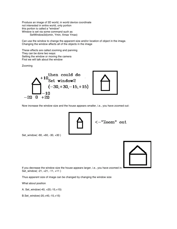

Produce an image of 3D world, in world device coordinate not interested in entire world, only portion this portion is called a "window" WIndow is set via some command such as SetWindow2d(xmin, Ymin, Xmax Ymax) Can use the window to change the apparent size and/or location of object in the image. Changing the window affects all of the objects in the image These effects are called zooming and panning They can be done two ways: Setting the window or moving the camera First we will talk about the window Zooming Now increase the window size and the house appears smaller, i.e., you have zoomed out: Set_window( -60, +60, -30, +30 ) If you decrease the window size the house appears larger, i.e., you have zoomed in: Set_window( -21, +21, -11, +11 ) Thus apparent size of image can be changed by changing the window size What about position
- A. Set_window(-40, +20,-15,+15)
B.Set_window(-20,+40,-15,+15)