
SLIDE 1
Proof of Concept Test of FBG (Fiber Bragg Grating)-based Pressure Transmitter
Byeong-Yeon Kim, Hyungmo Kim, Youngil Cho, and Jewhan Lee Korea Atomic Energy Research Institute, Daedeok-daero 989-111, Yuseong-gu, 34057, Republic of Korea.
*Corresponding author:byeongyeon@kaeri.re.kr
- 1. Introduction
In recent years, FBG (Fiber Bragg Grating) has attracted a lot of research interest due to its potential benefit to sensor applications [1-3]. A FBG-based pressure transmitter over a wide range of temperature and low pressure range is being developed at KAERI (Korea Atomic Research Institute). In the sensing scheme, a FBG is strained by pressure through a diaphragm, and it produces shift of the Bragg
- wavelength. Thus, pressure can be measured by
monitoring shift of the wavelength. Compared with conventional pressure sensors, the FBG-based sensor has the advantages of high resolution, easy to be cascade, and having no effect on electromagnetic field. The developed pressure transmitter has potential to be applied to various liquid metal systems with high temperature and low pressure range since there is few pressure transmitter for those systems. In this paper, we have provided proof of concept of a prototype of FBG-based pressure transmitter.
- 2. Proof of Concept Test of FBG-based Pressure
Transmitter 2.1 Overview of a Prototype of FBG-based Pressure Transmitter The prototype of FBG-based pressure transmitter is shown in Fig. 1. The FBG-based pressure transmitter is composed of two FBG elements for discrimination between pressure and temperature. The first element is for measuring wavelength caused by system pressure from diaphragm deformation and that caused by temperature of the FBG element. The second element is
- nly for measuring wavelength caused by temperature
- f the FBG element. Thus, pressure without the effect of
temperature can be calculated from the wavelength measurements of two FBG elements. The specification
- f the prototype of pressure transmitter is shown in
Table I.
- Fig. 1. The prototype of FBG-based pressure transmitter
Table I: The Specification of the developed pressure transmitter
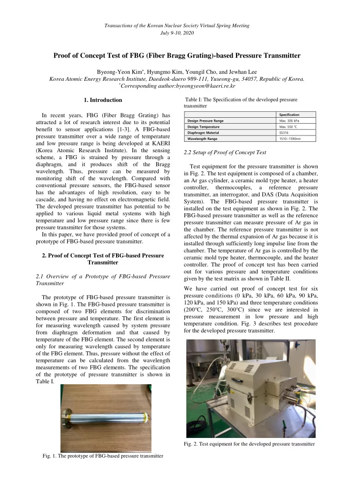
2.2 Setup of Proof of Concept Test Test equipment for the pressure transmitter is shown in Fig. 2. The test equipment is composed of a chamber, an Ar gas cylinder, a ceramic mold type heater, a heater controller, thermocouples, a reference pressure transmitter, an interrogator, and DAS (Data Acquisition System). The FBG-based pressure transmitter is installed on the test equipment as shown in Fig. 2. The FBG-based pressure transmitter as well as the reference pressure transmitter can measure pressure of Ar gas in the chamber. The reference pressure transmitter is not affected by the thermal expansion of Ar gas because it is installed through sufficiently long impulse line from the
- chamber. The temperature of Ar gas is controlled by the
ceramic mold type heater, thermocouple, and the heater
- controller. The proof of concept test has been carried
- ut for various pressure and temperature conditions
given by the test matrix as shown in Table II. We have carried out proof of concept test for six pressure conditions (0 kPa, 30 kPa, 60 kPa, 90 kPa, 120 kPa, and 150 kPa) and three temperature conditions (200℃, 250℃, 300℃) since we are interested in pressure measurement in low pressure and high temperature condition. Fig. 3 describes test procedure for the developed pressure transmitter.
- Fig. 2. Test equipment for the developed pressure transmitter
Specification Design Pressure Range
- Max. 300 kPa
Design Temperature
- Max. 550 ℃
Diaphragm Material SS316 Wavelength Range 1510~1590nm