Developing Component-Based Software for Real-Time Systems - - PDF document

developing component based software for real time systems
SMART_READER_LITE
LIVE PREVIEW

Developing Component-Based Software for Real-Time Systems - - PDF document

Developing Component-Based Software for Real-Time Systems zyxwvutsrqponmlkjihgfedcbaZYXWVUTSRQPONMLKJIHGFEDCBA Orlarido: FL 32816-2450: US.4 zyxwvutsrqponmlkjihgfedcbaZYXWVUTSRQPONMLKJIHGFEDCBA Abstract


slide-1
SLIDE 1

Developing Component-Based Software for Real-Time Systems zyxwvutsrqponmlkjihgfedcbaZYXWVUTSRQPONMLKJIHGFEDCBA

(2) zyxwvutsrqponmlkjihgfedcbaZYXWVUTSRQPONMLKJIHGFEDCBA

+

Controller - (1)

  • jority. if not all: models and applications. Due to the

Janusz Zalewski School of Electrical Engineering & Computer Science University of Central Florida Orlarido: FL 32816-2450: US.4 zyxwvutsrqponmlkjihgfedcbaZYXWVUTSRQPONMLKJIHGFEDCBA

jzaC!ece.engr.ucf.edu

Plant

Abstract zyxwvutsrqponmlkjihgfedcbaZYXWVUTSRQPONMLKJIHGFEDCBA

T h i s zyxwvutsrqponmlkjihgfedcbaZYXWVUTSRQPONMLKJIHGFEDCBA

paper discvsses the principles of developing softwax cornportents for real-time systems. The proce-

durx is zyxwvutsrqponmlkjihgfedcbaZYXWVUTSRQPONMLKJIHGFEDCBA

bused on the fu~~dorrierital

concept of U real-time ai.ciiitectwe rooted in the feedback contial puradigm of cor~tivl

  • eiiyirieeiiiig. Genevic desi,qn pattenis for r e d

tirrie softwwe coinponents are presented: valid for all

The rest of this paper is structured as follows. First, we discuss a generic architecture of real-time software. Then: we develop a pattern for one type of applica- tion; a data acquisition system. Next, we present a case study of a sophisticated air traffic control system viewed as a data acquisition system, and finally outline the development of software components with the use

  • f off-the-shelf design and implernentatiori tools.

Ailoderri real-time systems can be all viewed as spe- cific instances of a general feedback control system pre-

based desi,yn arid iiripleirientation is pesented, iriclud-

1n.y i7ldusti~y-sti.erigth

c o ~ n ~ n e r ~ i a l

  • ff-the-shelf software.

1

Introduction

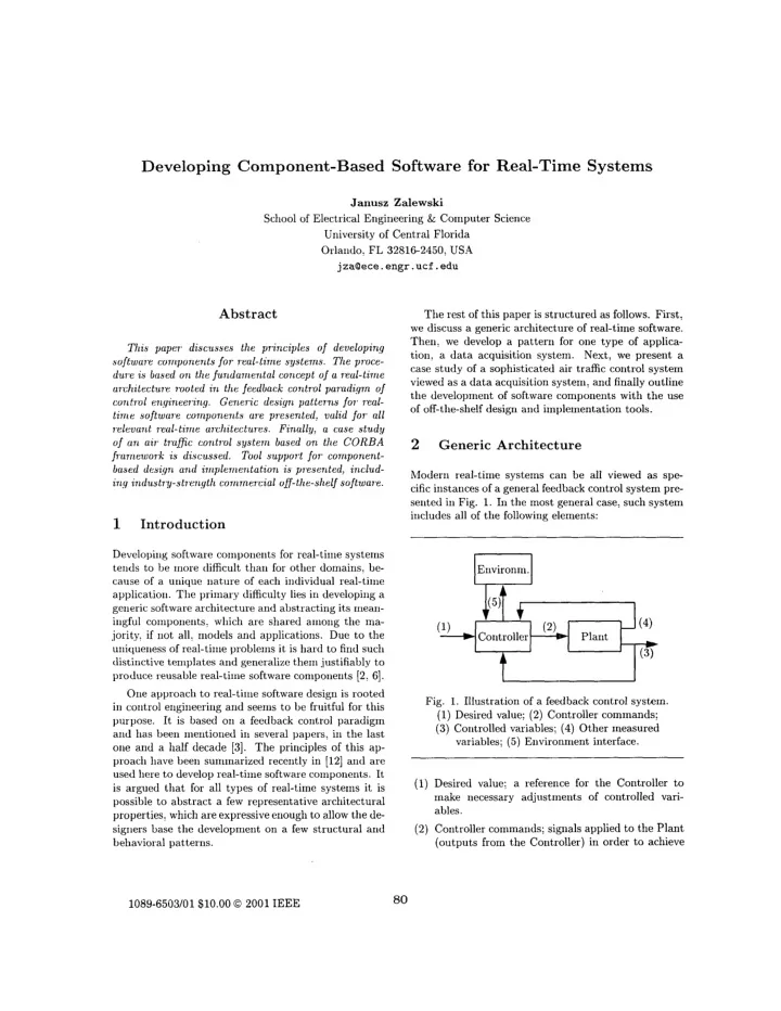
serited in Fig. 1. In the most general case, such system iiicludes all of the following elements: Developing software components for real-time systems teiids to be more difficult than for other domains: be- cause of a unique nature of each individual real-time

  • Environrn. zyxwvutsrqponmlkjihgfedcbaZYXWVUTSRQPONMLKJIHGFEDCBA

c l

One approach to real-time software design is rooted

in control engineering and seeiris to be fruitful for this

  • purpose. It is based 011 a feedback control paradigm

and has been mentioned in several papers, in the last

  • ne and a half decade [3]. The principles of this ap-

proach have been summarized recently in [12] and are used here to develop real-time software components. It is argued that for all types of real-time systems it is possible to abstract a few representative architectural properties, which are expressive enough to allow the de- signers base the developnient on a few structural and behavioral patterns.

  • Fig. 1. Illustration of a feedback control system.

(1)

Desired value; (2) Controller commands;

(3) Controlled variables; (4)

Other measured variables; (5) Environment interface. (1) Desired value; a reference for the Controller to make necessary adjustments of controlled vari- ables. (2) Controller commands; signals applied to the Plant (outputs from the Controller) in order to achieve 1089-6503/01$10.00 0 2001 IEEE

80

slide-2
SLIDE 2

its desired behavior. Controlled variables; signals received from the Plant (inputs to the Controller) whose values are being controlled. Other measured variables; auxiliary signals re- ceived from the plant (inputs to tlie Controller) wliich are riot controlled but used in the deteririi- IiatioIi of tlie best values of Controller CoIriiriaIids. Eiivironriient interfaces zyxwvutsrqponmlkjihgfedcbaZYXWVUTSRQPONMLKJIHGFEDCBA

  • user iiiterface. mass stor-

age interface. arid corrimuriication link to computer network. Because of the timirig requireIiieIits (such as time coristarits) imposed OII tlie controller dynamics, it al- ways operates in real time. Since nowadays a controller is iiripleniented as zyxwvutsrqponmlkjihgfedcbaZYXWVUTSRQPONMLKJIHGFEDCBA

a digital processor arid its furictioii-

ality can be exterided iiiucli beyoIid that of a regulator fiuictiori: we can call it a real-time computer. It is also evident that in addition to a traditional iiiterface a controller has to the process (which includes seiisors arid actuators)

~ a modern real-time computer

interacts with the eiiviroiiIrieiit in a ~iurriber

  • f other
  • ways. iriclucliIig iriterfaces with a plaiit operator, mass

storage (database)

~ aiid computer network. zyxwvutsrqponmlkjihgfedcbaZYXWVUTSRQPONMLKJIHGFEDCBA
  • 4

more detailed view of these interfaces is presented in a unified diagram shown iri Fig. zyxwvutsrqponmlkjihgfedcbaZYXWVUTSRQPONMLKJIHGFEDCBA

2 .

q&p

Computer

  • Fig. 2. Real-time computer system. (1)

User int.erface; (2) Process iiiterface; (3) Mass storage interface; (4) Coiiirriuriicatiori link.

111 practice: a number of real-time systems exist that

do riot represent a complete sys,teiri in a sense of Fig.

  • 1. but nevertheless fit very well into this concept. Re-

spective examples iriclutle: zyxwvutsrqponmlkjihgfedcbaZYXWVUTSRQPONMLKJIHGFEDCBA

0 data acquisition system: when the connection 2 in

  • Fig. 1 is broken (there is no coutrol signals from

the real-time computer.)

0 prograrrirned controllers. when tlie feedback con-

Iiectiori in Fig. 1: from the plant to the coritroller: is removed: with corinection from the controller to the plant remaining intact

0 reduced architecture, if both connections between

a plant and a real-time computer are broken (what remains is only interfaces with the operator: the network and the database). While the examples of real-time systems in the first two categories are intuitively clear: existence of the last category may be less obvious. However, taking a closer look at respective dataflows reveals that there are several examples of that kind of real-time systems in practice. Putting emphasis on the distribution arid cornmunicatiori, with relatively less interest in GUI and database access, brings us to a typical case of real-time

  • simulation. With a slightly different emphasis, con-

centrating 011 tlie database use a ~ i d GUI, one has a real-time Iriultirriedia system.

3

Real-Time Design Patterns

Orice we have an understandiiig of the nature of a real- time system architecture, we can focus 011 developing its design arid shaping its software architecture. How-

  • ever. thus far: there lias been very little guidance 011

selecting real-time architectures: either in the engineer- ing literature or in practice. When one takes a closer look at Figures 1

and 2: with explanations (1)-(5)

in the previous section: there is little doubt that one can arid should start desigiiirig the coiitroller from the context diagram similar to that iri Fig. 3. Real-Time co1riputer User Teririirial Output #1

I rriput #1 1

  • Fig. 3. The top level context diagram.

81

slide-3
SLIDE 3

The role of a context diagram cannot be overesti-

  • mated. Even though it is a relatively old notational

vehicle, it's been well established in real-time software design as the basis for architectural development. It is at the context diagram level, where the interfaces be- tween the software and the external world need to be defined and developed. For this very reason: the con- cept of a context diagram is indispensable as a starting point in designing a software architecture. Fro~n Figure zyxwvutsrqponmlkjihgfedcbaZYXWVUTSRQPONMLKJIHGFEDCBA 3: it becomes immediately clear that the software components must include units responsible for the following interactioiis with all external elernerits: inputs from and outputs to the plant interaction with a user possible comrriunicatiori with

  • t,her

controllers/ processors iriteraction with storage devices eiihariced by the processing (coiriputatiod) capability. The time source is also irIiportaIit arid can be iIiterIial

  • r external tlepeiidiiig OII circumstances.
  • Fig. 4. Outliiie of a generic

data acquisition system. zyxwvutsrqponmlkjihgfedcbaZYXWVUTSRQPONMLKJIHGFEDCBA

,

Store Collect Timer G U1 D.4Q Software Sen- sors

, 4 1 1 example of a correspoIidiIig design, which can

be considered a basic arid generic design pattern for real-time software, is presented in Fig. 4: for a data acquisition application. Respective software components need to cornply with the principle of separation of concerns. They can be considered as sequential modules or iIidividua1 con- current tasks, and can run: respectively: on a single pro- cessor, OII multiple processors: or even 011 a distributed system or network. This basic design pattern can be expanded further into more corriprehensive architectures, depending on the focus of a particular application, such as a dis- tributed real-time system. DepeIidiIig on a pretlonii- riaiit furictioii of a distributed system: oiie may pro- duce a variety of its particular architectural instances. One such example (Fig. 5) coIiies from the area of high- energy physics, where multiple data collection arid con- trol facilities are spread over a large area surrouriding a11 elementary particle accelerator [5].

.......... .....

. . . . . . . . . . . .

.

.... ...........

.....

..';.. ....

:,.

......

. .

. , zyxwvutsrqponmlkjihgfedcbaZYXWVUTSRQPONMLKJIHGFEDCBA

  • I. ........

'

.....

j

Exueriirient Hardware Laver

.

.... .... Other Devices eiisors ........

  • Fig. 5. Generic architecture of a distributed real-time

system. Multiple software components can be created to ac- cess various (maybe the same) sources arid destinations

  • f data and to exchange information among themselves.

.kIiY single corripoIient can perform individual functions and communicate with every other component. .4ddi1ig a new coIiipoIient or deleting one should have 1

1 impact or Iriinirrial impact 011 the operation,

iIi a sense that 1

1 degradation of functionality should

  • ccur due to such dynarriic changes. Communication

links caii operate individually or be lumped into a mid-

82

slide-4
SLIDE 4

dleware layer [7], with program units communicating partially or exclusively via this layer. The primary advantage of having such a flexibility is that a number of new components can be created and the architecture expanded during the run of an ex- periment or operation of a process. One such example is a dynamic GUI creation [SI. If new experiments are conceived which require including additional features to the GUI, or new characteristics are explored which need GUI reorganization, this can be done on-the-fly without jeopardizing the operation of an ongoing ex- periment or process. zyxwvutsrqponmlkjihgfedcbaZYXWVUTSRQPONMLKJIHGFEDCBA

4 zyxwvutsrqponmlkjihgfedcbaZYXWVUTSRQPONMLKJIHGFEDCBA Detailed Design Level

For the concept of real-time design patterns: as pre- sented in previous section, to work properly: one must provide enough details at the desigil level, so that au- tomatic tools could be used. The details mean: in the first place: providing sufficient inforrriation about inter- faces with the environment. The format involves the following items: zyxwvutsrqponmlkjihgfedcbaZYXWVUTSRQPONMLKJIHGFEDCBA

0 signal iianie as a variable (that is; expressed in 0 its source and direction (input or output) 0 signal's detailed function 0 its detailed characteristics, including data type

(analog, binary, text: etc.) zyxwvutsrqponmlkjihgfedcbaZYXWVUTSRQPONMLKJIHGFEDCBA

, range of valid values,

length, shape, frequency, etc. (whatever applica- ble)

0 necessary action in case of invalid value, whicli ef-

fectively means an error handling function. acceptable textual format)

To illustrate principles of creating detailed designs:

starting with such interface description, we will use an example of instrumentatiori software for testing printed circuit boards (PCB). Let's assume that a PCB stand is interfaced to the following three instruInents necessary to operate the board and take respective measurements to test it: power supply: spectrum analyzer and data acquisition box. zyxwvutsrqponmlkjihgfedcbaZYXWVUTSRQPONMLKJIHGFEDCBA

  • 4

context diagram for the iristrurnentatiori software is shown in Fig. 6, limited to the signals exchanged with the above instruments (a plant, in terminology o f

  • Fig. 1). -4 sample list of signal interfaces, exchanged

with the plant, is presented in Table 1, following the description format above. Once the exact description of input and oputput sig- nals is known: a detailed and complete list of actions in terms of operations ori all signals has to be developed. I

IInstrumentation Software

  • Fig. 6. PSB test system context tliagrarri.

This list can be obtained from the require~rierits spec- ification document. .

4

sample reyuirerrierit related to the value of SuPPLY-1 is presented below. but the full list of actions had to be omitted from this article due to space restrictions. Table 1. Detailed signal description (notes are too long to fit in the table). zyxwvutsrqponmlkjihgfedcbaZYXWVUTSRQPONMLKJIHGFEDCBA Reyui~ement

  • X. Y.Z. I

f SUPPLY-1 current exceeds the

value specified in Note 2, then the testing prograrri shall do the following:

0 turn the power supply voltage B+

  • ff

83

slide-5
SLIDE 5

0 zyxwvutsrqponmlkjihgfedcbaZYXWVUTSRQPONMLKJIHGFEDCBA

display the value of SUPPLY-1 in the message win- dow as follows: "SUPPLY-I zyxwvutsrqponmlkjihgfedcbaZYXWVUTSRQPONMLKJIHGFEDCBA

too high: value"

0 append the value of

SUPPLY-I to the file

results. txt,

and

0 stop the operation;

  • therwise it shall continue. zyxwvutsrqponmlkjihgfedcbaZYXWVUTSRQPONMLKJIHGFEDCBA

End X .

Y.2

Even though we are using such a simple example and have deliberately limited interface description to the plant interface only: leaving out information on the remaining three interfaces from Fig. zyxwvutsrqponmlkjihgfedcbaZYXWVUTSRQPONMLKJIHGFEDCBA 2, for the sake

  • f brevity: this single requirement contains references

both to the GUI (talking about the message window) arid to the database (talking about appending value to the file).

At this point, we are ready to define the structure

arid behavior of tlie software: in our example, the in- strumentation software. Because testing printed circuit hoards is a process sequential by nature, tlie structure

  • f the iristruirieritatioii software is also sequential. Fol-

lowing the generic architectural pattern from Fig. 4, we need to distiiiguish the following sequential modules in

  • ur design corripoiient: .4cquisition arid Control, GUI,

Storage Haridler, and hlaiii Computation. Knowing that there are three separate external devices in the plant connected to the real-time computer, we'll need to create three correspoiiding instances of the Acqui- sition arid Control module: Power Supply: Spectrum Analyzer, and Data .4cquisitiori Box. For completeness, we have to inention two things re- garding the generic pattern froin Fig. 4. There is 110 need for us to have a Comrriuiiicatiori Link, because

  • ur testing system is starid-alone. We will most likely

be using time orily locally, so the Timer module is not needed either. .4s a result, our componerit will have a relatively simple structure and can be easily repre- sented as a class diagram, with objects listed in the previous paragraph. However, we riiust be aware that in general, the developer would have to design con- current modules, according to the generic pattern from

  • Fig. 4, and define precisely respective interfaces among

these modules. For a large systerri, this is likely to be- come a daunting task and will be illustrated briefly in the next section. One last thing, which the designer has to do is defin- ing each Iriodule's behavior. For a sequential system like our iristrumentatioIi software, the behavior can be easily derived from the list of actions produced above in terms of operations on respective signals, and rep- resented as a sequence diagram. For more complex systems with concurrent niodules, this has to be done formally using statecharts.

Air Traffi

5 Case Study: Air Traffic Control System

Let us consider the design of software for an air traffic control system (-4TCS) conceived as a data acquisition system [9]. It is not: in fact, an automatic control sys- tem, because there is no direct connection between the real-time computer and the plant. ,

4 1 1 commands are

executed by the pilot who is receiving respective mes- sages from an air-traffic controller (Fig. 7).

  • Fig. 7. .4ir traffic control system as a data acquisition

system.

4 1 1 example of the context diagram for the air traf-

fic control system is presented in Fig. 8. It is fully compatible with the general model (Fig. 3). External .4TCS Software zyxwvutsrqponmlkjihgfedcbaZYXWVUTSRQPONMLKJIHGFEDCBA

W k ,

Database I Sources J

  • Fig. 8. The top level context diagram for an air traffic

control system.

84

slide-6
SLIDE 6

A zyxwvutsrqponmlkjihgfedcbaZYXWVUTSRQPONMLKJIHGFEDCBA component-based software architecture derived from this context diagram is presented in Fig. 9. Indi- vidual boxes represent software modules interfacing to the external devices and performing respective func-

  • tions. The architecture is also compatible with the

software design pattern shown in Fig. 4 arid includes modules responsible for handling: three sources of data (radars: GPS arid time zyxwvutsrqponmlkjihgfedcbaZYXWVUTSRQPONMLKJIHGFEDCBA

0 a user interface to controller displays 0 two functionally different mass storage interfaces

(for flight plans and event recording) two furictionally different network interfaces (for zyxwvutsrqponmlkjihgfedcbaZYXWVUTSRQPONMLKJIHGFEDCBA

en zyxwvutsrqponmlkjihgfedcbaZYXWVUTSRQPONMLKJIHGFEDCBA

i ~ v u t e

centers and weather services)

0 coinputatio~ial

function, which in this case is orily collisioIi detection but may iiiclucle altitude warii- iiigs, proximity wariiiiigs: etc. source; the latter is not shown) GPS

Network connectivity via middleware s/w bus zyxwvutsrqponmlkjihgfedcbaZYXWVUTSRQPONMLKJIHGFEDCBA

t it

Radar

  • Fig. 9. ATCS software compoiieiits coiruriuiiicatirig

via iriiddleware. Since tlie nature of the system is highly distributed: we use Iiiiddleware for coiiriectiIig all the coniporierits. This gives the tlesigiiers the highest flexibility in orga- riiziiig individual corriporierits and shaping their co111- inunicatioii structure.

6

Components Development: Design Aspect

Developing software coIripoIielits for the presented

.4TCS arcliitecture or other contemporary real-time ap-

plications, such as the one described in (51 is too coni- plex to be done rria~iually by a single iiidividual. There- fore autoriiatic tools are needed to assist in the devel-

  • jmierit process.

It must be stressed that tools are orily a part of a complete design methodology which must include the

  • Fig. 10. Sample object diagram in a high-level design

tool Rhapsody. following three elenieiits: inetliod (a grapliical notation to express properties of an architecture)

, techniques

(traiisfomiatioIis applied to the notation)

~ and software

tools support,irig the traIisforrriatioii techniques.

To be useful in tlie development of software co~ripo-

iierits we require the automatic tools to provide support in the following dirrieiisioIis [12]:

0 iutcriial, to express real-time models via the spe-

cific notation and respective traIisformatioIis to create real-time coiiipoiieiits

0 horizontal, related to means of coIIiiriuiiicatioii 0 vertical, related to the next and previous phases 0 diagorial, related to tlie use of architectural com-

with other components arid other tools

  • f the developirieiit process

ponents in Jiffererit projects/processes.

111 a language of software colriporielits this means we

have to be able to create, connect, model: a ~ i d reuse corriporieiits at the design level. Several software tools with this concept iIi ~iiiiid, which operate iii the coniiriercial marketplace, were an- alyzed [l]. For practical reasoris: we focused on those, which have solid methodological foundatioiis: based on

00 approaches: ROOM [lo] arid UML [4].

The selected tools offer extensive services in the in- ternal dimension to model both structural and behav- ioral patterns of distributed real-time software. The structure arid behavior of a comporieiit such as the Conini Link from Fig. 9 can be easily expressed as an object diagram arid a statechart, respectively (Fig. 10 arid 11). In the horizontal diirieiisiori, a capability

  • f interacting with externally created corriporieiits is zyxwvutsrqponmlkjihgfedcbaZYXWVUTSRQPONMLKJIHGFEDCBA

85

slide-7
SLIDE 7
  • Fig. 11. Statechart for a sample COIIIIII

Link module

iri Rhapsody.

  • Fig. zyxwvutsrqponmlkjihgfedcbaZYXWVUTSRQPONMLKJIHGFEDCBA
  • 12. hiIodehg corriiriuIiicatiori with exter~ial

coIripoIients in ObjecTirrie. provided for most tools via standard TCP/IP protocol (Fig. 12). Iri the vertical dirneiisiori, tools usually have the ca- pability of generating code for specific real-time keriiels, however, they lack the capability to perform timirig analysis at the design level. They also lack adequate iiieaiis of importing design compoiients from other tools (diagonal dimerision). zyxwvutsrqponmlkjihgfedcbaZYXWVUTSRQPONMLKJIHGFEDCBA

7 Components Development:

Implementation Aspect

At the irriplemeiitatiori level: the design tools should allow timing and scheduling analysis: then correcting the design, arid fiiialy code generation. With current tools, timing analysis is only possible after the code has been generated. For this reason: when developing the basic ATCS structural components and defining their behaviors: it

  • Fig. 13. HaIidlirig load stress by MPI, R/lPI/RT,

CORB.4 arid RT-CORBA. turns out that a rriuch more rigid coIniIiuiiication struc- ture is necessary for the whole design, to ensure timeli- ness axid predictability. Traditionally, coiriinuiiicatioIi

in distributed applications is doiie via sockets or remote

procedure calls (method invocation). This is very iri- adequate for distributed real-time applications. Therefore two iIIipleIrieIitatiori level standards for distributed real-time coiriIiiuIiicatioii were studied: MPI/RT and Real-Time CORB.4. simple real-time betichrriark: to haiidle load stress from the sensors, was designed and ruii under four stardards: MPI (iripich) zyxwvutsrqponmlkjihgfedcbaZYXWVUTSRQPONMLKJIHGFEDCBA

: CORBA4

(Visibroker): i\IPI/RT (from Missis- sippi State) and RT-CORBA/T.%O (Wasliirigtou Uriiv.,

  • St. Louis). Perforniance results for 1iandliIig IiiaxiIiiuIIi

corriIriuiiicatioii load by these tools are presented in Fig.

13 [ll] (for a network of Sun Ulka 2's ruIiiiirig Solaris

2.6). It is evident that MPI shows geiieral perfoririaiice superiority over CORBA4, however: with much less flex- ibility for coiripoIieIits creation.

,411 additional study with the same beiichiiiark was

done to investigate meeting deadlines. VLr1ieIi a task is busy with collecting data frorn :sensors: it may riot be able to respond on time to other needs for computation. This situation was simulated by requesting a collecting task work in zyxwvutsrqponmlkjihgfedcbaZYXWVUTSRQPONMLKJIHGFEDCBA 5 sec. intervals to gather 100 sensor data items (reasonable for -4TCS) and record the followiiig (Table 1): Table 2. Comparison of deadline behavior. Java sockets 1098 111s 427 111s 4 Ills \'genic CORBA 778 111s 494 1 1 1 s zyxwvutsrqponmlkjihgfedcbaZYXWVUTSRQPONMLKJIHGFEDCBA

0 the riumber of times a 5.1 sec. soft deadline was

86

slide-8
SLIDE 8

missed (SD misses) zyxwvutsrqponmlkjihgfedcbaZYXWVUTSRQPONMLKJIHGFEDCBA

References zyxwvutsrqponmlkjihgfedcbaZYXWVUTSRQPONMLKJIHGFEDCBA

0 the total amount of time a hard 5.0 sec. deadline

was missed (HD misses). All experiments were run in Java under Solaris 2.6 (on Ethernet), except of C sockets, which were run for Vx- Works. In summary, the results of experiments prove that for real-time components to work properly the design phase has to take into consideration the real-time im- plementation standards (such as MPI/RT and RT- CORBA) for the distributed target platforms. Includ- ing implementation related design patterns into design- level description will greatly simplify the process of de- signing real-time components.

8

Conclusion

We tried to provide evidence that there is a clear template for real-time software architectures arid de- sign patterns, historically rooted in control erigirieer- ing, that allows designers to build software components for complicated real-time systems using conirriercial off- the-shelf tools. The development process consists of several steps, including: the precise definition of signals interfacing with the environment, description of required actions

011 all these signals: and building respective structural

and behavioral diagrams, with the use of automatic tools, if necessary. Applying these concepts and tools to a complicated air traffic control system confirmed this view arid re- vealed ‘the directions of additional work needed to enhance timing analysis at the design level arid al- low importing design components. Nevertheless, ex- isting principles arm the developers of real-time soft- ware components in a set of invariants that they can successfully use in their development practice. A.H.M. AlMazid, zyxwvutsrqponmlkjihgfedcbaZYXWVUTSRQPONMLKJIHGFEDCBA

Engineering Analysis of Object- Oriented Software Development TooJs zyxwvutsrqponmlkjihgfedcbaZYXWVUTSRQPONMLKJIHGFEDCBA

for Distributed

Real-Time Systems, hl.Sc. Thesis, Univ. of Central

Florida, Orlando, Fla., zyxwvutsrqponmlkjihgfedcbaZYXWVUTSRQPONMLKJIHGFEDCBA

2000

  • L. Bass, P. Clements, R. Kazman, Software Archi-

tecture in Practice, Addison Wesley, Reading, hlass.,

1998

  • hl. Boasson, Control Systems Software, IEEE Trans.
  • n Automatic Control, 38(7):1094-1106, July 1993

B.P. Douglass, Doing Hard Time: Developing Real-

Time Systems with UML, Addison-Wesley, Reading,

Mass., 1999

  • K. Gaspar, B. Franek, J. Schwarz, Architecture o

f a Distributed Real-Time System to Control Large High- Energy Physics Experiments, Parallel and Distributed

Computing Practices, 2(

1):103-114, March 1999

G.T. Heineman, W.T. Council1 (Eds.), Components-

Based Software Engineering, Addison-JVeslev, Boston,

hlass., 2001

  • C. hlufioz, J. Zalewski, Architecture and Performance
  • f Java-Based Distributed Object Models, Real- Time

Systems Journal, 21(1/2):43-76, July 2001

  • H. Pedroza, GUI Builder for Real- Time Dastributed

Object Models, hl.Sc. Thesis, University of Central

Florida, Orlando, Fla., 1999 hl.T. Pozesky, M.K. hlann, The US .4ir Traffic Control System .4rchitecture, Proc. of the IEEE, 77(11):1605-

1617, November 1989

  • B. Selic, G. Gullekson, P.T. Wad, Real-Time Object-

Oriented Modeling, John Wiley and Sons, New York,

1994

S Su, Benchmarking Distributed Real- Time Applica- tions, hl.Sc. Thesis, University of Central Florida, Or- lando, Fla., 2000

  • J. Zalewski, Real-Time Software .4rchitectures and

Design Patterns: Fundamental Concepts and Their Consequences, Annual Reviews in Control, zyxwvutsrqponmlkjihgfedcbaZYXWVUTSRQPONMLKJIHGFEDCBA

25( 1):133- 146, July 2001

87