THE DESIGN OF A CFRP CHOPPER DISC FOR A TIME OF FLIGHT SPECTROMETER - - PDF document

the design of a cfrp chopper disc for a time of flight
SMART_READER_LITE
LIVE PREVIEW

THE DESIGN OF A CFRP CHOPPER DISC FOR A TIME OF FLIGHT SPECTROMETER - - PDF document

18 TH INTERNATIONAL CONFERENCE ON COMPOSITE MATERIALS THE DESIGN OF A CFRP CHOPPER DISC FOR A TIME OF FLIGHT SPECTROMETER V.Antonelli 1 *, M. Wedekind 1 , L. Krmer 1 , H. Baier 1 1 Institute of Lightweight Structures, Technische Universitt


slide-1
SLIDE 1

18TH INTERNATIONAL CONFERENCE ON COMPOSITE MATERIALS

1 Introduction The time-of-flight (TOF) method is commonly employed in many scientific experiments involving neutron scattering. It allows the investigation of a great variety of topics, e.g. diffusive processes in liquids and melts, high-frequency acoustic propagation, optical vibrational modes, magnetic excitations and tunnelling spectroscopy. Chopper discs are used in neutron TOF technique [1]: a pulsed monochromatic beam strikes the sample, and the energies of scattered neutrons are determined by their time of flight to an array of detectors as shown in Fig. 1.

  • Fig. 1. Schematic plan of the time of flight

spectrometer TOF-TOF at FRM II [2] Chopper discs rotate around an axis parallel to the neutron beam, reaching speeds up to 22,000 revolutions per minute. They can either be used to pulse the beam or as well be used as velocity filter, in order to monochromatize the beam (TOF-TOF method, see Fig. 1). Acting as neutron selectors, their filtering ability is enhanced utilizing neutron absorbing materials. The area directly in contact with the beam of the disc presented in this paper is coated with an anti neutron coating. Therefore only neutrons travelling across the neutron-transparent apertures (or slits) are extracted from the incoming beam. In order to improve the performance of the time-of- flight spectrometer, wider and faster discs are

  • required. Originally the discs were made of metal

alloys, but as in the last decades, when higher speeds and larger diameters have been required, fibre composites are preferred, due to their high specific strength. The Institute of Lightweight Structures of the Faculty of Mechanical Engineering (Technische Universität München) has been producing and designing CFRP chopper discs for over a decade, specialising in faster and lighter designs with various aperture designs.

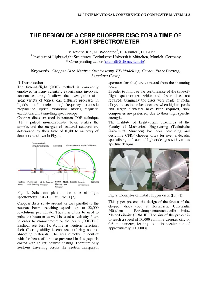
  • Fig. 2. Examples of metal chopper discs ([3][4])

This paper presents the design of the fastest of the chopper discs used at Technische Universität München

  • Forschungsneutronenquelle

Heinz Maier-Leibnitz (FRM II). The aim of the project is to reach a speed of 30,000 rpm in a chopper disc of 0.6 m diameter, leading to a tip acceleration of approximately 300,000 g.

THE DESIGN OF A CFRP CHOPPER DISC FOR A TIME OF FLIGHT SPECTROMETER

V.Antonelli1*, M. Wedekind1, L. Krämer1, H. Baier1

1 Institute of Lightweight Structures, Technische Universität München, Munich, Germany

* Corresponding author (antonelli@llb.mw.tum.de)

Keywords: Chopper Disc, Neutron Spectroscopy, FE-Modelling, Carbon Fibre Prepreg, Autoclave Curing

slide-2
SLIDE 2

2 List of requirements The important characteristics of a chopper disc are its diameter, its design speed and its maximum mass, limited by the driving mechanism. A further important characteristic, given for each disc, is the amount and geometry of the apertures, providing the neutron-transparent apertures. Other boundary conditions concern the attachment of the disc to the driving mechanism, the collar. In the introduction it is mentioned that the area, where the neutron beam passes through, needs to be neutron absorbent. In this way the neutrons can pass

  • nly through the opening apertures. Like aluminium,

the performance of CFRP to absorb the neutrons is not sufficient; therefore, in this area an anti neutron coating, e.g. based on boron (10B), is applied. 3 Chopper disc design 3.1 Definition of cross-sectional geometry of a full disc The cross section of the composite design is similar to the metal one, having a decreasing thickness with increasing distance from the rotating axis. This is based on the Grammel’s criterion [5], used e.g. for sizing of flywheels. This criterion allows designing a high-speed rotating disc of a varying thickness and constant stress. A high speed rotating disc is represented Fig. 3 using a series of annular discs of constant thickness.

  • Fig. 3. Representation of Grammel’s criterion on an
  • ptimized rotating disc

According to [5] it is possible to calculate the

  • ptimal geometry of a rotating disc starting from an

elementary disc with a constant thickness. The stress field of the first rotating disc is given by: Where A, B, C and D are constant which are function of the geometry and of the angular velocity. This method is iterative and it allows designing a disc with equal stresses at every section interface. Choosing an initial value of it is possible to calculate . Using these stresses it is possible to determinate the four constants. Then it is necessary to calculate the stress gap between the first disc and the second one. Imposing the following conditions:

(1)

It is possible to find the stress gap: v

(2)

Reflecting the convergence with infinitesimal small ring elements the stress gap is getting zero. With this the optimal configuration of a rotating disc with constant strength is obtained. Due to design restriction shown later, this shape cannot directly be

  • applied. Yet, the final design is based on the optimal

shape, regarding the functional requirements of the system. 3.2 Restrictions on cross-section of chopper disc As mentioned above, the Grammel’s criterion is valid in the case of an undisturbed disc, while in the actual case the chopper is required to have a certain number of apertures. These openings can either be very narrow and long or very short and wide; depending on the specific use and spectrometer design. The number of apertures, their width and opening radius are given requirements, while the fillet (see

  • Fig. 4) has to be designed according to strength

consideration.

  • Fig. 4. Geometry of the aperture
  • pening angle

fillet

slide-3
SLIDE 3

3 PAPER TITLE

The aperture’s geometry is one of the most important design limits that have to be taken into

  • account. The cross section of the disc, in fact and the

position of the fillet (see Fig. 4) determine the material that has to be used and the fibre layup. Further restrictions are provided by functional requirements, e.g. the design of the driving mechanism and its connection to the chopper disc or adaptors needed for balancing. An overview of the functional requirements is shown in Fig. 5. In particular, the disc has to have a constant thickness in the areas with high mechanical loads and functional elements. Due to strength issues the interference of stress concentrations and interlaminar shear stresses caused by changing stiffness must be

  • avoided. These effects limit the possible tapering

areas and angles of the disc.

  • Fig. 5. Overview of functional requirements of the

chopper disc An anti-neutron coating is used to allow a sufficient absorbing performance. Due to the high acceleration loads, the coating must have sufficient mechanical

  • properties. Furthermore, the resin system used must

be chemically compatible with the prepregs resin

  • system. The coating is applied on the whole outer

ring, as shown in Fig. 5. The stiffness of the coating is negligible compared to the composite. Therefore, from a structural point of view, it is only adding further mass, increasing the load on the bearing structure. 3.3 Material selection Possible materials to choose are metal or CFRP. The advantages of metallic materials are its isotropic material properties. Compared to CFRP, this relaxes the criticality of the design restrictions. Compared to metal alloys, CFRP has a higher specific strength and better fatigue behaviour, resulting in a more lightweight disc. The effort to manufacture large components is minor compared to high strength alloys. The cross-section of the chopper disc is defined by the layup and the mould. Therefore, only minor milling is required after

  • curing. Furthermore, the knock down factors for

high strength metals increase drastically with increasing thickness of the workpiece. Therefore, CFRP was chosen as material. In the tapered areas, the stiffness changes cause interlaminar shear stresses, which are especially critical when interfering with in plane stress

  • concentrations. Due to these mechanical issues, a

prepreg with a consolidated thickness of 0.125 mm is chosen, enabling a smother tapering, thus resulting in significantly lower interlaminar shear stresses. Furthermore, ply drop-off in the critical areas is done interleaved. The load case of the disc is axis symmetrical; therefore, also axis symmetrical layers (with either radial or circumferential fibres) could be taken into

  • account. In literature examples on optimisation of

flywheels are shown, resulting in axis symmetrical fibre orientation [6]. In contrast to a flywheel, the stress field in a chopper disc is disturbed by the apertures, resulting in complex states of stress. These require several reinforcing fibre directions in the fillet areas. Taking this and the manufacturing difficulty of a complex laminate with prepreg technology into account led to the choice of a quasi isotropic layup. 3.4 Production considerations The chopper disc design is based on consideration of specific stiffness and strength, therefore a composite material high fibre volume content is preferred. Due to the expertise present at LLB on autoclave manufacturing and the good performances of composites manufactured with this production technique, prepreg and autoclave curing have been chosen. Manufacturing the discs, using prepreg technology with autoclave curing induces restrictions, limiting the possible designs, as prepregs only provide one fibre orientation per layer with predefined ply

  • thickness. Furthermore the stiffness of the prepregs

limits the drapability, having an impact on feasible stacking sequences of non-developable areas.

Aperture Balancing drill holes Adaptor for collar Coatedarea (10B4C+resin) cocured Stepping (discrete) Plateau (functionally required) Stepping (smooth)

slide-4
SLIDE 4

Due to the strongly orthotropic properties of a single layer, several restrictions have to be taken into account within a ply drop off, limiting the tapering angles [7]. Steep tapering angles induce shear stresses in the weak perpendicular direction, causing premature failure. This effect limits in conjunction with restrictions caused functional areas required the maximal tapering angles and therefore the possible cross sections of the discs to a small set of parameters.

  • 4. Layup and shape and optimisation

The rotation causes an axis symmetrical loading on the disc and stress concentrations in the fillets resulting in a complex, multi axial stress field. Like mentioned, therefore, a quasi isotropic stacking was

  • chosen. The outer ring of the disc having a small

thickness is prone to out-of-plane distortion. Due to residual curing stresses caused by the temperature difference between curing and

  • peration,

a symmetric layup is required. To guarantee robustness with regard to temperature loads, a 180°C resin system is chosen. Several studies have been carried out in order to define the best cross section, taking into account both design and manufacturing requirements. In the beginning the cross section of an

  • ptimal

undisturbed disc was looked at, as mentioned in chapter 3 [8]. Based on this design, considering the shown restrictions caused by application and manufacturing, a tailored disc design was developed. Beside the adaptor for the collar, the geometry of the window fillet causes the peak stresses in the disc and therefore limits the performance. To find the best geometry for the fillets area, resulting in a smooth stress distribution, a numerical optimisation was carried out.

  • 5. Production

The production of the disc is carried out at the institute with pre cutted rings of pre-pregs centred

  • n a stacking mandrel. Curing of the rotational

symmetric raw disc is performed in an autoclave, using a closed steel splitted mould. The boron coating is co-cured during this process. Trimming of the disc and fabrication of the features like windows and balancing holes is performed in a milling process.

  • 6. Testing

High speed rotating tests have been carried out on five chopper discs with the same design requirements in order to verify the influence of the fillet design and layup on the ultimate strength of the

  • disc. The tests have been performed in a vacuum

chamber to avoid a temperature increase due to aerodynamic friction. The test stand has a shielding being strong enough to catch the fragments of a failing disc.

  • Fig. 6. Chopper disc mounted to test rig

Only these full-scale tests provide reliable data on the performance of an entire disc. The major drawback of a full scale test is the limited information on the onset of failure. At the test site used, no direct observation during the test was possible. The goal of the test is to determine the failure speed. During the test the speed is increased in steps to check for damage growth. Since, as mentioned, an instrumentation of the failing disc is difficult the vibration of the disc is measured during the test. In the case of aberrations during the test, the test is interrupted and the vessel is opened in order to visually check for failures. Premature failure leads to a change of the balancing of the disc and therefore increases the vibration. Examples for premature failure are delaminations due to improper window fillet design or spalling of the coating, which can be caused by manufacturing problems.

Drive Chopper Shielding

slide-5
SLIDE 5

5 PAPER TITLE

  • Fig. 7. Behaviour of vibration during ultimate speed

test In Fig. 7 the speed and vibration plot during a test of a disc without premature failure is shown. The plot

  • f the vibration shows a high level at a speed of

12,500 rpm caused by the resonance frequency of the whole system.

  • Fig. 8. Manufactured chopper disc with collar and

balancing adaptors The overall curve is similar to the amplitude frequency response of a single mass oscillator. Beyond the single resonance frequency, the amplitude response of the system is continuously dropping with increasing speed and, therefore increasing excitation frequency. To exclude manufacturing flaws causing a catastrophic failure in utilisation, the strength of all discs used in the TOFTOF spectrometer is verified

  • experimentally. The discs are operated with a

margin of safety to ensure a high safety and exclude fatigue issues.

  • 7. Conclusions

Each disc is designed according to the specific requirements of the TOF-TOF spectrometer. After autoclave curing the final geometry is created via

  • milling. Every disc produced is tested. During

testing the discs vibration response is observed to detect damages. Future work will focus on application of modern materials and optimisation of boundary conditions induced by interfaces, like the geometry of the collars adaptor. This work will be done in collaboration with the manufacturer of the driving system and operator of the TOF-TOF instrument. References

[1] J.R.D.Copley and T.J. Udovic “Neutron Time-of- Flight Spectroscopy” Journal of Research of the National Institute of Standards and Technologies,

  • Vol. 98, No1, pp 71-87, 1993

[2] http://www.frm2.tum.de/en/science/spectrometry/toft

  • f/schematic-assembly (8. June 2011)

[3] http://norbert.mit.edu/reactor/fac_chopper.html (25. May 2011) [4] http://www.ncnr.nist.gov/programs/CHRNS/Chopper 3Dmodel.png (25. May 2011) [5] C.B. Biezeno , R. Grammel “Engineering Dynamics”, Blakie and Sons, London 1954 [6] B. Fabien, “The influence of failure criteria on the design

  • ptimization
  • f

stacked-ply composite flywheels”, Structural and Multidisciplinary Optimization, Vol. 33, Issue 6, pp. 507-517, 2007 [7] A. Mukherjee, B. Varughese, ”Design guidelines for ply drop-off in laminated composite structures”, Composites Part B: Engineering, Volume 32, Issue 2, pp 153-164, 2001 [8] T. Pühlhofer, H. Baier, L. Krämer, T. Unruh, "Design, Manufacturing and testing of high speed rotating CFRP chopper discs", SAMPE EUROPE International Conference 2006, 27.-29. March 2006, Paris

10 20 30 40 50 60 70 80 90 100 5000 10000 15000 20000 25000 30000 Failure Speed [RPM] Vibration [%] Resonancefrequency